zuirgham
Junior Member level 3

I'm Designing an alarm interface circuit, which is one of the small part of a ventilator machine. This is an external alarm interfaced as a remote alarm, in case nurse is in different room. If there is some error, the alarm goes ON.
I have no idea what the general interface looks like / have inside the alarm circuit, so that i can plan my design accordingly.
I just know it should be normal connected(N.C). , interface connector Should be 8pin RJ45, Thats all. What data to send, which protocol to be used, im just blank for now.
I was thinking of using relay to Switch between Normal open and Normal closed, But no idea what data to send, etc.
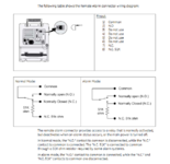
I found something relevant on internet, please see the image attached.
Could Anyone guide me on this on how to proceed with designing circuit for this ?
I have no idea what the general interface looks like / have inside the alarm circuit, so that i can plan my design accordingly.
I just know it should be normal connected(N.C). , interface connector Should be 8pin RJ45, Thats all. What data to send, which protocol to be used, im just blank for now.
I was thinking of using relay to Switch between Normal open and Normal closed, But no idea what data to send, etc.
I found something relevant on internet, please see the image attached.
Could Anyone guide me on this on how to proceed with designing circuit for this ?