Continue to Site

Welcome to EDAboard.com

Welcome to our site! EDAboard.com is an international Electronics Discussion Forum focused on EDA software, circuits, schematics, books, theory, papers, asic, pld, 8051, DSP, Network, RF, Analog Design, PCB, Service Manuals... and a whole lot more! To participate you need to register. Registration is free. Click here to register now.

Adding adjustable pulse frequency and duty cycle to this PWM circuit

MIAB

Newbie level 5
Newbie level 5
Joined
Jan 23, 2025
Messages
10
Helped
0
Reputation
0
Reaction score
0
Trophy points
1
Activity points
57
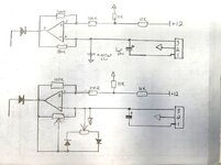
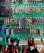
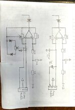
Is it possible to add two potentiometers to this circuit to be able to adjust frequency and duty cycle of this PWM circuit. At connector 13 (bottom) there is connected a 3 way (on-off-on) switch. When switched to 1+2 it is 2 cycles/s. When 2+3 it is no pulsing with 0 cycles/s. When switch in middle position (only 2) it is 200 cycles/s. This is in an Ac/Dc tig welder. I would like to be able to vary the pulses from 2-200 and better yet 0.1-200/second.

Thank you

1000002255.jpg


[MODERATOR ACTION]
  • Rotate original image to portrait aspect
 
Last edited by a moderator:
Hi,

I´d surely use a microcontroller solution.
Every (even a small 8 pin) microcontroller should do a better job regarding range, accuracy, stability...

Klaus

Btw: the blury picture is hard to read, and using portrait format makes it worse.
.png picture format is smaller and yet higher quality than .jpg when showing schematics.
I don´t know how you inserted this picture ... please use the [Insert Image} button.
 
Thank you for your reply. I was hoping for a simple analog solution with a potentiometer for pulse control from 0.5hz to the 200hz max it does now instead of just the 2hz or 200hz choice it gives me with the 3 position switch. Would putting a pot in the +12v sawtooth wave signal work (+) or does it have to be on the modulating signal (-) side? Is it possible in an analog way to adjust duty cycle as well? I don't need precision just adjustability.

The later models of my welder have the pulse adjustability and duty cycle built in. As well as AC frequency control.

I am a beginner but very technical in interest. Thanks again
 
Would putting a pot in the +12v sawtooth wave signal work (+) or does it have to be on the modulating signal (-) side?

Depends on how the PWM circuit was implemented. Do you have a schematic you can post ?

If you go here and search on "pwm generator" some pretty cheap solutions including LCD :

www.aliexpress.com


Seems like most of them limited to 1 Hz min though. I did not examine every one however.

Note this can be done with a micro board quite easily, some programming though.
--- Updated ---

Another possibility (you have to write a little code, ~ 25 lines of code :

1738078493465.png


Note single chip solution, given a welding environment, takes a knowledgeable person
to manage, not so much the above circuit, but the high currents and arc strike radiated EMI
and noise coupling issues that occur around welder/cutters.
 
Last edited:
Thank you for all your responses. I've attached the PDF of the circuit diagrams. Page 9 is the one I showed a clip from. Sorry, I am not able to clip all the other pages out from my phone for ease of viewing.

I was hoping to avoid add-on boards or circuits. I understand I might be silly because of your elegant choices above. I was really just hoping to add a couple pots to the front panel and tie into the circuit board.

Thanks again!
 

Attachments

  • Service-Manual-BOC TIG185 D5.pdf
    2.1 MB · Views: 29
Your oscillators appear to be ordinary relaxation type. By installing potentiometers and diodes in strategic places you have adjustable frequency and duty cycle.

relaxation oscillator slow op amp 2 pots 2 diodes (adjust Freq n duty cyc).png


Link below runs schematic in Falstad's animated interactive simulator:
You can alter a potentiometer during run.

tinyurl.com/243v6ony
 
What repeatability and accuracy do you want for your settings ?

Over what ambient T range do they have to work ?

Is this a one off welder fix or several in a shop that settings repeatability have
to apply to all in the shop ?
 
Thank you for that. I feel like I am getting much closer. Very cool simulation.

In this case is my image accurate for what I need to do? The values have me stumped. Top is the original, bottom is my understanding of what needs to be done. I am sure it's wrong. Please advise.

Thanks again
 

Attachments

  • 20250128_155318.jpg
    20250128_155318.jpg
    669.8 KB · Views: 17
Danadakk, the newer model machine that have this convenience of adjustable pulse and duty cycle just have a switch to turn on pulse and then two pots (frequency, duty) with a very primitive dial indicating 0-200hz. There is no accuracy at all. The accuracy comes from the actual welding and going up and down slightly to get the good results. We would be working in - 20c to +40c environment. It's just my single machine but all friends and colleagues have the same machines. They would probably want me to help them do the same if it works for me. Thing is that this machine does pulse stick welding but the newer machine does not. It would be very handy for stick as well.

Thanks
--- Updated ---

If this helps.
--- Updated ---

I changed my hand drawn image above. I changed to a 2 way switch and what I think connection 1-2 should go. 2-3 is pulse off, 1-2 pulse on.
 

Attachments

  • 20250128_161122.jpg
    20250128_161122.jpg
    1.5 MB · Views: 28
  • 20250128_163154.jpg
    20250128_163154.jpg
    799.7 KB · Views: 29
Last edited:
They would probably want me to help them do the same if it works for me.
This is where you start treading on a minefield. Of course you hope to be helpful to friends and colleagues. Yet as soon as you touch someone else's machine, you're married to it. Even if you succeed once, the other guy thinks you're skilled enough to fix anything that goes wrong (related or unrelated). Anyone and everyone might turn to you to open their machine to make other 'improvements.'

Are these welders supplied by your workplace? Your employer may be aware whether BOC offers warranty work, or retrofitting (not that I know). That pcb looks crowded. Any mistake on your part might result in a broken welder. I don't believe it should show any sign that you worked on it, unless you can afford to buy an updated model.
 
Thanks Brad. You are correct that it is crowded. This is my personal machine. I don't work as a welder but I do alot of it. BOC no longer makes or supplies parts for these unfortunately. These machines are more robust and build quality is miles ahead of the newer models. It welds a dream. The pulse stick is really where it stands apart. 2 hz is usable, 200hz is not. Ideally I can adjust from 0-10 or so for stick. Tig would be great for the full 0-200hz.

I would try to make the above circuit recommendation off the board (epoxy board) and then hardwire it to the board at the appropriate spots. Enough room for that I think.
 
You wish to obtain a range of 1:1000 (0.2 to 200 Hz). You may decide it's easier to split this into two ranges, each covering 35x (0.2 to 7Hz, and 6 to 210). In other words you may decide to re-purpose your 3-position switch, by including another capacitor of suitable value. This will require revising your oscillator circuit.

Another factor is whether you want to use a logarithmic potentiometer. I have wondered how much a potentiometer's dialing curve can be modified by attaching a resistor (or resistor network) across its terminals. The possibilities are numerous yet tedious to test in regard to performance.
 
Thanks Brad. If I was looking for instrument level pulse response then I think you absolutely correct (split into multiple bands). Welding is anything but exacting. I would need another digital screen to get the actual pulse. In effect 0.2 is really the same as 0.8 and 30 is really the same as 45. If you get what I mean, it's really not exacting.

Do you think I am on the right track in the circuit I drew? Do you see any obvious mistakes?

Thanks again
 
Any further steps must be made by exploration and experimentation. The switch connector is labelled 1-2-3 yet your schematic ought to show what further circuitry it goes to. Already you might have two capacitors because you state the unit gives you 0.2 Hz on one setting and 200 Hz on the other setting.

Your oscillator frequencies are governed by the RC time constant. You plan to revise this by making the R figure variable. I believe somewhere near the op amp IC you'll find a low Ω resistor that yields 200 Hz. And a high Ω resistor that yields 0.2 Hz. These become guides for your min/max values. You also need to identify the capacitor (and any other capacitor which gets switched into the circuit). You need to desolder one or more components so you can attach different combinations of components. Going by raw math your potentiometer must add from zero to 1000 X the lowest Ω you find in the circuit. Adjustments require a steady hand.

That is enormous range and you'll be lucky if oscillations sustain at every setting. This starts to look like a lot of effort. You must preserve a balanced interaction among resistors and capacitors if you want variable frequency and variable duty cycle.
 
Thanks Brad ,It might be that your 555 timer IC idea earlier in the thread might be the the ay to go. I will do some research about it. Thanks
 
I was hoping for a simple analog solution with a potentiometer
now it´s days later.... still it seems you have no working solution. Even now that you lowered your standards regarding range and accuracy.

With a microcontroller ... you would be finished since days!
* the hardware is minimal: microcontroller (even better if you use a module like an arduino nano), capacitors, pot. nothing else.
(even without a module it´s maybe 5 electronic parts. Soldered - even if you are not expereinced - within a couple of minutes.
* the software can be downloaded form internet .. just needs to be adjusted on range.
That´s what I call a simple solution. (Way less parts, way less to solder,

Yet it does not need to lower your standards. It does perfectly what you initially wanted.

****
If I´m not mistaken most analog solutions suffer from the problem that the "frequency adjustment" also (unwanted) influences the duy cycle and vice versa. This does not happen with a digital solution. If you adjust the duty cycle to (let´s say) 15% .. it will stay at 15% .. not 16%, not 14%.

But - in case you want to - software wise you have the flexibility for the duty cycle to adjust to frequency. You just input the according formula and it does what you want.
No soldering of new part values, no modification of schematic ..

Don´t get me wrong: I´m by far not the person who wants too abolish the analog technology. No, it has it´s benefits, and I like to use these benefits.
In most of my applications I use both combined: analog and digital circuits.

*****
But for sure it´s your way to do things, your time, your stress, your money ...

I´m not forcing you to do what you don´t want to do.
I just want to give you a part of my experince - that I gained during decades of professional electronics design.

Klaus
 
Of course the advantage to using a micro, besides repeatability, accuracy, is ability
to store, enter, edit, and share, some standard settings, like for materials, amongst
you and your friends.

Could even share this with friends via web if they all used the same solution......
 
Last edited:


Write your reply...

LaTeX Commands Quick-Menu:

Part and Inventory Search

Welcome to EDABoard.com

Sponsor

Back
Top