Continue to Site

Welcome to EDAboard.com

Welcome to our site! EDAboard.com is an international Electronics Discussion Forum focused on EDA software, circuits, schematics, books, theory, papers, asic, pld, 8051, DSP, Network, RF, Analog Design, PCB, Service Manuals... and a whole lot more! To participate you need to register. Registration is free. Click here to register now.

Adding a varicap to a vfo, what is the best point?

Status
Not open for further replies.

neazoi

Advanced Member level 6
Joined
Jan 5, 2008
Messages
4,155
Helped
13
Reputation
26
Reaction score
15
Trophy points
1,318
Location
Greece
Activity points
37,164
I have this vfo **broken link removed**
and I would like to add a varicap to it. How should I add it?
 

The varicap is first put in series with a fixed capacitor, and then the combination is put in parallel with the variable capacitor of the VFO.

The purpose of the series capacitor is to have a value chosen such that the series combination with the varicap will alter the VFO capacitor by a calculated desired amount, and also it provides a DC isolated place at which to bias the varicap with a control voltage. The smaller the series capacitor, the less effect the varicap will have.
Choice of this capacitor gives fine control of the tuning range.

If you want the whole value of the varicap available range to affect the tuning, then simply make the series capacitor large enough to make the series combination be nearly all from the varicap, but keep the benefit of having a place to connect the resistor-isolated bias.

Since your VFO has switched range inductors, you may need a varicap circuit for each range.
 
Thank you, I will try this and let you know.
I am going to use a vfo stabilizer that requires:
The VFO has varicap control allowing a tuning range of ±3 kHz to be produced by a control voltage swing of 5 V (2.5 V = centre tuning).
Any thoughts avout what varicap to use? I have an MV209, would that be ok?
 

The VFO has varicap control allowing a tuning range of ±3 kHz to be produced by a control voltage swing of 5 V (2.5 V = centre tuning).
Any thoughts about what varicap to use? I have an MV209, would that be ok?
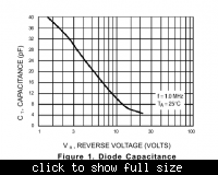
MV209 has a useful range starting at about 35pF (bias 2V) through to about 6pF (bias 12V).
You can see the bias scale is logarithmic non-linear. You get more capacitance change when the bias centre voltage is low. you will see later what a big advantage feature this can be.


The next part you have to do with your calculator or spreadsheet. This is like a recipe :)

I can see the VFO main tuning capacitor is 20-350pF. I cannot see any additional varicap tuning, unless I misunderstand the circuit.

We need to know either the frequency ranges covered, or the value of the range inductors.

Either way, you need to use Freq ~= 1/(2*pi*SQRT(L*C)), for the the VFO tuned at C=350pF, and estimate L.
Do it again for C=20pF, estimate L. Easy enough, knowing the highest and lowest for all the ranges.

Make a spreadsheet plot using that formula, and figure how much change in the capacitance you add across the variable C to get the 2-3kHz fine control you want. It will be a tiny amount.

Now use C_added=(1/C_series) + (1/C_varicap) OR C_added = (C_series*C_varicap)/(C_series + C_varicap).
Yes - you need some algebra to turn it into an expression fo C_series. Try (product)/(difference) I think.

Keep in mind that the shift in kHz will be much more at the high end of the ranges, because the change you add is a larger proportion of the C in the VFO circuit at that point. Notice that the MV209 non-linear characteristic works for you to very nearly counter this effect, delivering less change for a given bias as the capacitance gets small. I suggest using a small Op-Amp circuit to allow you to set the centre of the bias (offset), and the span (gain), and feed the output through a high-value (100K) to the varicap

That's about it. I don't know any more on this. There are bound to be some new situations you learn as you try to do this. The recipe is very much a "provided nothing goes wrong" scenario. It is just a starting plan.

Good luck
 
Thank you very much for this useful info! I will try it along with some experimentation to see how it goes and let you know.
The varicap will be first put in series with a fixed capacitor, and then the combination is put in parallel with the variable capacitor of the VFO.
Then feed the varicap with a stable 7.5v max voltage through a 100k resistor (for current limiting?) and a shunt 0.1uF cap at the resistor end that connects to the 7.5v psu side.
The mv209 can go to about 25v, so I loose the 4-13pF non linear portion, but I already have a stable psu on 7.5v and I do not think it will cause so much problem for the stabilizer.
 

That diode has a 5:1 max:min cap ratio for 12:1 Voltage ratio or an abs. values of 40:8 pF
Since ∂f is proportional to SQRT C
then SQRT(C) ratio is 6.3:2.8 affect on ∂F so choose a mid range operating point of the average of those two.. or 9.1/2=4.55 which now squared is ~ 20pF.

To maximize ∂F the fix series capacitance needed to be 20 pF in series. Any error in tuning needs a shunt cap which of course reduces the cap Max:min ratio of tuning.

That's off the top of my head from 30 yrs ago.

p.s. of course any bulk signal diode will work and possible with higher C max:min ratios but are generally too inaccurate to rely on for nominal.

If you have a PI C-L-C resonator circuit a differential dual varicap gives even more pull range and better linearity, at the expense of needing a dual amp rail-rail differential voltage control in a bridge cap ratio circuit. ( hmm sounds weird)
 
  • Like
Reactions: neazoi

    neazoi

    Points: 2
    Helpful Answer Positive Rating
Status
Not open for further replies.

Part and Inventory Search

Welcome to EDABoard.com

Sponsor

Back
Top