umery2k75
Advanced Member level 1

sensor reading adc 0804 *.pdf
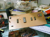
I designed a temperature sensor circuit, built with LM35 and ADC0804 and after that EPROM for Voltage->Centigrade conversion after that two BCD decoders and 2 seven segments. This circuits shows accurate temperature from 0'C to 99'C.
At the time this picture was taken, temperature was around 28'C which is quite comfortable.

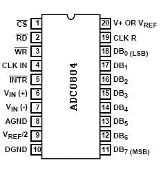
I came across two grounds as you can see in the PIN configuration, one is Digital Ground(DGND)and other is Analog Ground(AGND), I read somewhere in the datasheet or in the application note of ADC0804, as seperate the two grounds together, don't connect analog ground with digital ground. I am energizing this circuit with bench power supply using +5V and Gnd terminal rated at 1.5Amps. So I am giving +5V and Gnd to circuit.I don't know what to connect with Analog Ground. So I connect the two grounds together. The circuit is complete and checked, it shows temperature with good accuracy, and the job is done.
But I think the story hasn't ended yet, I think as the change in analog value was slow in this design, that's why I might have not run in trouble. What if high speed Analog to Digital conversion was going on, I might have run into a serious problem with Analog and Digital ground connected together, so tell me what to do with the Analog Ground, I can't leave it just unconnected.

I designed a temperature sensor circuit, built with LM35 and ADC0804 and after that EPROM for Voltage->Centigrade conversion after that two BCD decoders and 2 seven segments. This circuits shows accurate temperature from 0'C to 99'C.
At the time this picture was taken, temperature was around 28'C which is quite comfortable.

I came across two grounds as you can see in the PIN configuration, one is Digital Ground(DGND)and other is Analog Ground(AGND), I read somewhere in the datasheet or in the application note of ADC0804, as seperate the two grounds together, don't connect analog ground with digital ground. I am energizing this circuit with bench power supply using +5V and Gnd terminal rated at 1.5Amps. So I am giving +5V and Gnd to circuit.I don't know what to connect with Analog Ground. So I connect the two grounds together. The circuit is complete and checked, it shows temperature with good accuracy, and the job is done.
But I think the story hasn't ended yet, I think as the change in analog value was slow in this design, that's why I might have not run in trouble. What if high speed Analog to Digital conversion was going on, I might have run into a serious problem with Analog and Digital ground connected together, so tell me what to do with the Analog Ground, I can't leave it just unconnected.


