Continue to Site

Welcome to EDAboard.com

Welcome to our site! EDAboard.com is an international Electronics Discussion Forum focused on EDA software, circuits, schematics, books, theory, papers, asic, pld, 8051, DSP, Network, RF, Analog Design, PCB, Service Manuals... and a whole lot more! To participate you need to register. Registration is free. Click here to register now.

ADC with Voltage Divider

Status
Not open for further replies.

ozcanay

Newbie level 6
Newbie level 6
Joined
Jul 22, 2016
Messages
13
Helped
0
Reputation
0
Reaction score
0
Trophy points
1
Activity points
139
Hi,

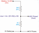
I am building an ohmMeter for my course project. I am trying to make use of voltage divider principle.
Ekran Alıntısı.PNG

Divider is given above. I am using STM32F429(12 bit ADC ->4096 max) and the voltage source is 3.3V . I am using 3.3k ohm(R1) pull up resistor. When I measure 3.3k ohm resistor I read the value of 2048 as expected. But when I try to measure for example 10k ohm, I am reading value that is so different from the expected one.

I have searched for the reason on the internet and came across this : measuring voltage across unknown resistor what is hyperbolically dependent on the measured resistance, so actual precision varies greatly over the range of values of unknown resistor.

My question is why it is hyperbolically dependent on the known resistor? Does it have something to do with ADC input resistance?

Thanks in advance.
 

It probably has more to do with the writer not being fluent in English.

Basically unless the know resistor is a high precision resistor (e.g. 0.1%) then your accuracy will vary according to that known precision.

If you use a 10% resistor you won't get better than 10% accuracy in the unknown resistor value and if that unknown resistor is off by 10% you'll have even worse accuracy. Play around with the math and see for yourself. Increase the 3.3K by 10% and see what you end up with as the unknown resistor of 10K if you vary the actual physical value as +/-10%.
 
I guess you are right, thanks. I thought there was some magic stuff here but I found logical what you said.

I have one more question abot this thread actually, here it goes :

If I want to measure 10 MegaOhms, am I gonna need some extra component (I guess I will) , since my voltage source is just 5V.
 

If you want accurate measurements use a Wheatstone bridge instead.

You can still measure a 10M ohm using your divider, but you need an accurate 3.3K resistor and enough resolution on your ADC. It would be better to have a larger known resistor to measure in the Mohm range.
 
Hi again,

I managed to measure the resistance as high as 20k with the suitable R1 resistance chosen. But I cannot measure the resistances above ~20kohm ( by considering precision values). My acquired ADC value is becoming so different than expected. For example when I want to measure 56k, the software says it is 44k. Is this because of a problem in ADC or what, I am stuck. Maybe this problem arises when the total series resistance value gets higher, I don't know. Any help appreciated.
 

Hi,
I may be on the wrong track, I have no idea how the STM32F429 works...: Have you measured the voltage going into the ADC with the 20k and also with the 56k? Maybe there is an over-range problem, but I doubt that is the case.
 

By "voltage" going into the ADC I guess you mean the "current" going into the ADC. If that's what you meant, no I haven't measured that. Thanks for the reply though.
 

it has some relationship with the sink current of ADC module you used,some times when ADC measure the voltage of the resistor divider,it will sink some current from the resistor divider and forms some voltage dropout if the resistance of the top resistor is big enough,so if you still can not get the right value you want ,you can replace the resistor with some small value and try again,hope it can help
 
Status
Not open for further replies.

Similar threads

Part and Inventory Search

Welcome to EDABoard.com

Sponsor

Back
Top