Continue to Site

Welcome to EDAboard.com

Welcome to our site! EDAboard.com is an international Electronics Discussion Forum focused on EDA software, circuits, schematics, books, theory, papers, asic, pld, 8051, DSP, Network, RF, Analog Design, PCB, Service Manuals... and a whole lot more! To participate you need to register. Registration is free. Click here to register now.

ADC voltage/current sensing

Status
Not open for further replies.

zhangz64

Junior Member level 3
Joined
May 1, 2013
Messages
25
Helped
0
Reputation
0
Reaction score
0
Trophy points
1,281
Activity points
1,632
Hi Everyone,

I am trying to use MSP432 on chip 14 bit ADC to sense output from a current sensing op-amp(https://datasheets.maximintegrated.com/en/ds/MAX44284.pdf).

I am getting a large reading error from my ADC compare to the multimeter reading.

My question is
Do i need to have a front end amplifier to buffer the input to ADC, or I can directly sense it?

Thanks a lot,
Eddy
 

You don't have to because that's what the opamp is for. But I don't know the specs of the internal ADC on MSP432, or how it is set up in MSP432. You're most likely giving it a weird reference voltage. If you have a nice test bench, you should sweep the current and look at the results. If the opamp and the multimeter has a constant difference but otherwise following the current change accurately, you have an offset error and it's actually not a big deal, you can even fix it in digital if you don't care about using the full scale range. If the ADC is giving weird data regardless you need more info to debug.
 
Hi,

The answer is in the two datasheets.
One tells you the input impedance / input current of the ADC,
The other tells you the drive capabilities (load resistance, output resustance, load current) of the amplifier.

My assumption is that therd is either a schematic error or a PCB routing issue.
--> show us your schematic and a picture of the PCB layout.
Additionally you should discribe your test circuit and the test results.

Klaus
 
Hi KlausST,

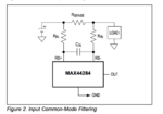
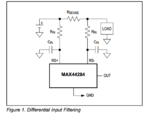
This may be a late reply. I did somehow manage to solve this issue by using a common mode filter at input and a filter at output. (I think the issue is that the noise get x100 amplified to the output, the ADC is picked up those noises)

Therefore, I do have some questions regarding the input filter design for this current sensing op amp.(MAX44284F)

Since, I am sensing the current on the LDO output rail. I am wondering what kind of noise would i expect to see there? Do i need both common mode filter and a differential filter at sense node ?

I would like to understand how does the common mode and differential mode filter works, why would a cap cross +/- terminals can reduce common mode noise?

Thanks a lot for your help,
Eddy
Screen Shot 2016-10-25 at 10.34.04 PM.png
Screen Shot 2016-10-25 at 10.33.58 PM.png
 

Attachments

  • Screen Shot 2016-10-25 at 10.28.08 PM.png
    Screen Shot 2016-10-25 at 10.28.08 PM.png
    71.5 KB · Views: 194

Hi,
All your informatins are vary vague:
I am getting a large reading error from my ADC compare to the multimeter reading.
DC? AC? What frequency?
What is "large"? For one a difference of 1mA is large, for the other 1A is large...

All the given circuits just reduce HF noise only, but none of them reduce low frequency noise.

You don´t give the requested informations of post#3.

None of your schematic gives values. Neither voltage, current, nor device values.


--> It´s impossible to help without the informations.


Klaus
 

Status
Not open for further replies.

Similar threads

Part and Inventory Search

Welcome to EDABoard.com

Sponsor

Back
Top