Georgy.Moshkin
Full Member level 5

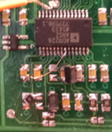
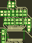
I have a design where AD9226 is used, and both experiencing similar problem:
when
1) MODE pin open: works (in this case "clock stabilizer" is disabled)
2) MODE to 5V: not working properly, distorted/scaled signal. Signal is scaled non-linearly depending on amplitude.
3) MODE to GND: not working properly, digitized data is zero
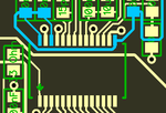
observed some strange voltage changes on noise reduction pins CAPB/CAPT
1) MODE pin open: CAPB=2.04V CAPT=3.08V (VREF=1.04V)
2) MODE pin to 5V: CAPB=3.72V CAPT=4.72V (VREF=1.04V) - this may explain why signal is distorted and "scaled"
3) MODE pin to GND: CAPB=0V CAPT=1.2V (VREF=1.04V) - here digitized signal shows only zero data
in my opinion clock stabilizer pin should not pull CAPB/CAPT voltages, although it may be normal.
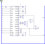
Using schematic from datasheet fig5.a single ended input, common mode voltage = 1v.

