DivadLarsen
Newbie level 3

Hello,
I have an issue with the AD8428 instrumentation amplifier, that looks like common mode issue, but I might be mistaking.
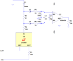
Basically I drive a custom laser diode using an LT3092 current source (basically a Voltage-to-current source in my application), and use the AD8428 to measure voltage across a 0.1R resistor in series with the laser. (See attached schematic)
The current measurement is needed in a 3.3V micro controller, hence the AD8428 ref-pin is grounded.
Since the laser Anode is inherently grounded, all driving is done from a -12V rail, which works well; Set-voltage and actual laser current has been verified using a multimeter.

However, when I measure the output of the AD8428 there's a non-constant error, depending on current through the sense resistor.
Below are some measurements of the set current vs the current measured using the AD8428:
mA set mA measured
1 0.869
2 0.1859
5 4.844
10 9.826
12 11.815
With a fixed gain of 2000, this translates into an offset error going from 26mV to 37mV from 1 to 12mA.
As the laser voltage increases with driving current it seems logical that the error increasing with current could be a common mode issue.
Now, I get that due to the high gain of 66dB, CMR is only ~74dB (CMRR=140dB), but that should still only be around 1mV error with roughly 5V across the laser.
Am I missing something, is my math off or am I just stright up an idiot?
NB: The AD8428 datasheet suggests 10M resistors to GND from inputs, but since that's used to create a GND-point for input offset currents, I figure that shouldn't be much of a problem with a constant connection through the LT3092.
(Also I did a quick test, which seems to verify this - but honestly I don't really trust ratsnests on high-gain, high impedance inputs ).
).
I have an issue with the AD8428 instrumentation amplifier, that looks like common mode issue, but I might be mistaking.
Basically I drive a custom laser diode using an LT3092 current source (basically a Voltage-to-current source in my application), and use the AD8428 to measure voltage across a 0.1R resistor in series with the laser. (See attached schematic)
The current measurement is needed in a 3.3V micro controller, hence the AD8428 ref-pin is grounded.
Since the laser Anode is inherently grounded, all driving is done from a -12V rail, which works well; Set-voltage and actual laser current has been verified using a multimeter.

However, when I measure the output of the AD8428 there's a non-constant error, depending on current through the sense resistor.
Below are some measurements of the set current vs the current measured using the AD8428:
mA set mA measured
1 0.869
2 0.1859
5 4.844
10 9.826
12 11.815
With a fixed gain of 2000, this translates into an offset error going from 26mV to 37mV from 1 to 12mA.
As the laser voltage increases with driving current it seems logical that the error increasing with current could be a common mode issue.
Now, I get that due to the high gain of 66dB, CMR is only ~74dB (CMRR=140dB), but that should still only be around 1mV error with roughly 5V across the laser.
Am I missing something, is my math off or am I just stright up an idiot?
NB: The AD8428 datasheet suggests 10M resistors to GND from inputs, but since that's used to create a GND-point for input offset currents, I figure that shouldn't be much of a problem with a constant connection through the LT3092.
(Also I did a quick test, which seems to verify this - but honestly I don't really trust ratsnests on high-gain, high impedance inputs
