voultsi
Newbie level 6

Hello people ,
I dont know if my question is under the correct category but anyway
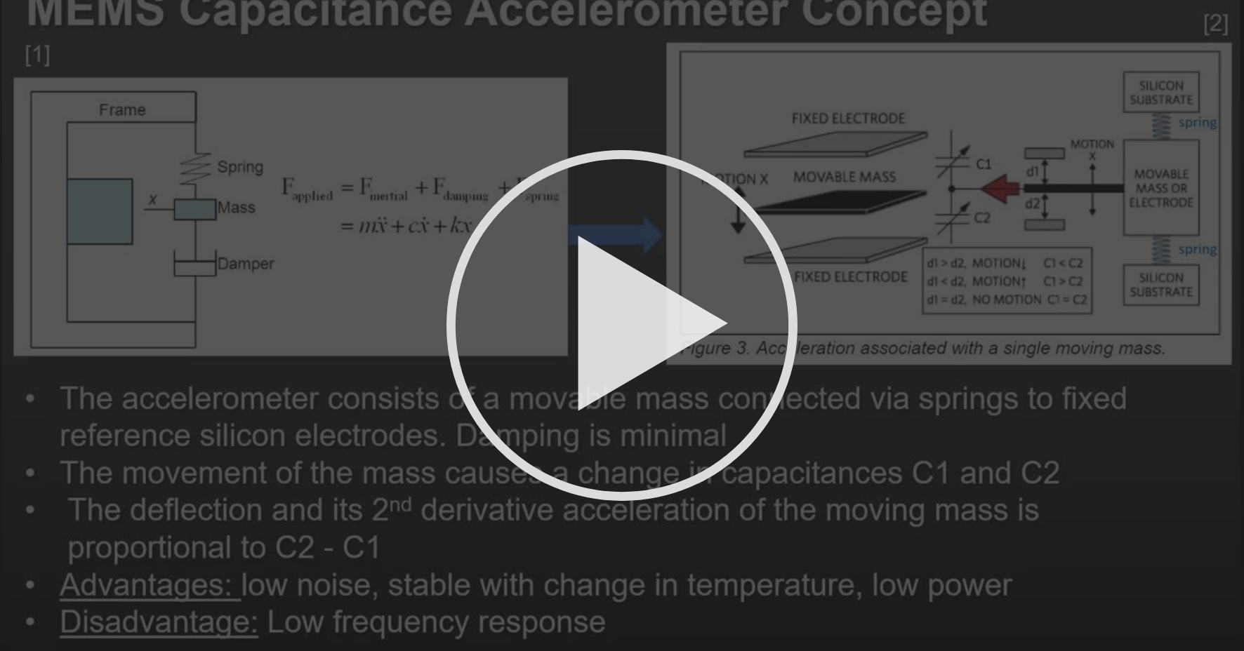
I need to design a very basic accelerometer circuit . The point is to take the voltage measuerement that a capacitive accelerometer provides and after proccessing it to output it .
The circuit will probably only consist of a few capacitors and resistors , an A/D converter ,an amp and integrators.
I have searched a lot online and have found very few info about such a topic , most are about the construction of the accelerometer. I have a some knowledge about op-amps(integrator,differentiator) and signals.
So if anyone can explain how and why things happen i would be very happy.
P.S i am talking about a diagram not any actual sensors , its more about understanding the concept


