Continue to Site

Welcome to EDAboard.com

Welcome to our site! EDAboard.com is an international Electronics Discussion Forum focused on EDA software, circuits, schematics, books, theory, papers, asic, pld, 8051, DSP, Network, RF, Analog Design, PCB, Service Manuals... and a whole lot more! To participate you need to register. Registration is free. Click here to register now.

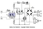
AC lamp dimmer using MOSFET PWM.

Status
Not open for further replies.
If you mind the amount of generated EMI, you'll add an LC filter to the circuit.
 

thank you for the replay.
please post a good LC circuit for 60W lamp PWM driving.
 

But where to put that LC filter?
 

if we use MOSFET without snubber due to spike and noise I hope it'll get damage.
how to protect MOSFET here or someother ckt/component acting as snubber here? or MOSFET won't get damage in this ckt?
Can any one clarify this pls.
 

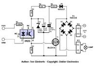
Damage to the MOSFET without a snubber is possible but far less likely than in a situation where it is used as a driver. In this schematic the voltage across the MOSFET is simply the rectified AC less any voltage dropped across the load. Essentially, it is being used as a variable resistor to set the current flowing through the bridge rectifier.

It should have LC filters on the connections to the the AC line and load as some of the PWM will inevitably modulate the line current. It would be interesting to investigate the effect of diode speed on this design. The 1N5408 specified in the design is not a fast device yet the MOSFET could be driven reasonably fast, I wonder where the switching losses actually occur.

Brian.
 

MOSFET_Dimmer ckt.jpg

I wanted to drive a fan about 80W 230V 50Hz
What should be the L1 value?
what type of core, coil thickness and number of turns?
capacitor is mandatory? where it should come across L1 or after L1 and its value?
 

I would suggest 100uH in both AC arms of the bridge and a class X2 275V AC 100nF capacitor across both the AC arms of the bridge and the line side of the inductors.

The filter will allow a small leakage current to flow so be careful!

Brian.
 

What if we use this ckt as a charger controlling the primary side of the transformer and rectifier on the secondary.
 

There's nothing stopping you doing that but it probably wouldn't be as efficient as a conventional regulator circuit.

Brian.
 

I used IRF840 instead of the shown mosfet but the mosfet is heating up after a few seconds. ( I am driving an exhaust fan)
 
Last edited:

What speed is the PWM?
Please note this is not a conventional PWM power switch, it uses the MOSFET as a controlled load across the bridge so the diodes should really be Schottky or fast recovery types. The bridge is there to make the MOSFET work equally with both polarities but the 'chopping' of the resulting DC across it is probably much faster than the diodes can cope with.

The test to confirm this would be to short out the output (transistor) side of the optocoupler. It should make the MOSFET conduct over the full PWM cycle and give you most voltage out. If the MOSFET runs cold it indicates a speed problem, if it still gets hot the problem is to do with insufficient gate voltage and it not becoming fully conductive.

Brian.
 

as per betwixt guess if the problem is due to in sufficient gate voltage there are three solution as far as my knowledge.
1. Opto-coupler LED has to be biased with higher current than now or rated current. For that R1 330ohm resistor has to be replaced with lesser value.
2. Reduce the PWM speed.
3. Replace D1 Zener diode from 10V to 15V or 18V zener diode.

pls someone clarify my doubt what can be the maximum PWM speed or operating frequency for 1N5408 diode?

- - - Updated - - -

I have searched many datasheet but I couldn't find 1N5408 operating frequench related information. what is the ON time and OFF time?
I could fine only Toatal Capacitance VR = 4.0 V, f = 1.0 MHz is 30pF
 

It's specified speed is >500nS at 200mA current although no actual value for recovery time is specified by any manufacturer. Clearly not suitable for fast operation. It is a standard recovery silicon rectifier and not intended to be used in an application where the load is switched at high frequencies.

Brian.
 

@betwixt: ur answer is so clear. but what can be the max PWM speed for this application? will it work for 1KHz or less than that. I'm designing this for controlling ceiling fan about 100W.
 

I wouldn't use it at all in that application, it is better suited to resistive loads than inductive ones. The recovery time of the diodes is constant whatever the PWM frequency and are the cause of them failing to switch properly. The losses are always there, all you can do is make them small compared to the length of the PWM cycle. I would suggest PWM of no more than about 400Hz before the losses become significant. The problem you will face is 400Hz and the line frequency are quite close and you may get strange fluctuations in output as you 'chop' the line signal at different parts of its cycle.

It is also worth considering that the motor in your fan may be synchronous so its speed would depend on the line frequency, not its voltage.

Brian.
 

If I run with 400Hz PWM frequency harmonics will be more and THD will be very high. Motor will get heat with humming due to this. Better to use high speed diodes or to go with phase angle control method.

It is Induction motor not synchronous (as far as I have seen ceiling fan with induction motor only). If it is synchronous motor Phase angle control technique or resistive regulator (old method) also won't work for fan speed control.
 

HI i am facing one of main issues in this circuit. The LED lamp is glowing once the opto stop conducting. Means the Zener makes the path of current flow to load. Is it any way to stop this?
 

HI i am facing one of main issues in this circuit. The LED lamp is glowing once the opto stop conducting. Means the Zener makes the path of current flow to load. Is it any way to stop this?
The circuit is consuming about 1 W in off state, and the leakage current would cause a LED or fluorescent lamp to glow or flicker. That's by design of this simple circuit and can't be stopped.

The circuit has many problems, e.g. that the MOSFET is driven into avalanche breakdown with any inductive load like the said fan motor. You can't stop this neither.
 

Status
Not open for further replies.

Similar threads

Part and Inventory Search

Welcome to EDABoard.com

Sponsor

Back
Top