I'm not familiar with Proteus, but you could try using the X-Y feature, taking the difference between the 2 phases of the mains source ( eg. A+B, internally inverting one of them ).
Follow along with the video below to see how to install our site as a web app on your home screen.
Note: This feature may not be available in some browsers.


There is no problem simulating this.

You can use the circuit below and scale it to your needs. It uses a 2.5 V offset so that the zero of your current measurement will be at 2.5 VDC. You can easily handle that in code to get your maximum and minimum readings.
The burden resistor that KlausST talked about is R1 in the diagram. It converts the current produced by the CT, to a voltage. The bandwidth of the circuit is about 300 Hz.
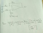
 Is this calculation is right way ?
How the design in the given circuit...

This is exactly as the circuit from post #8.How the design in the given circuit ?
I mean its calculation ?
[...]Is this calculation is right way ?
Most of the circuits in google telling that There should be a resistor to the ground ? It is easy to calculate the gain ?
Or he can add a DC blocking capacitor and do not need to do anything.It uses a 2.5 V offset so that the zero of your current measurement will be at 2.5 VDC. You can easily handle that in code to get your maximum and minimum readings.

Most of the circuits in google telling that There should be a resistor to the ground...


Very useful post
Thannara123 did you found extact values for your design?
Can you share your design for learning purpose

The circuit may satisfactory work for the OP.Can you share your design for learning purpose