ANALOGous
Newbie level 4

- Joined
- Oct 14, 2008
- Messages
- 7
- Helped
- 1
- Reputation
- 2
- Reaction score
- 0
- Trophy points
- 1,281
- Activity points
- 1,327
Hi,
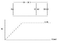
can anyone help to analyze the circuit shown below?
The clock is 10V : 50KHz signal. What I was thinking is because of the series resistors, Capacitor should charge up 5V ( =10/2).
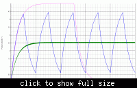
But when simulated, the voltage across capacitor settles at 2.5V with very small ripple. So can anyone explain why cap settles at 2.5V (not at 5V)?
I tried to analyze it but did not understand.

--
Thanks.
can anyone help to analyze the circuit shown below?
The clock is 10V : 50KHz signal. What I was thinking is because of the series resistors, Capacitor should charge up 5V ( =10/2).
But when simulated, the voltage across capacitor settles at 2.5V with very small ripple. So can anyone explain why cap settles at 2.5V (not at 5V)?
I tried to analyze it but did not understand.

--
Thanks.


