Pastel
Member level 3

Hello!
I'm not sure this is the proper place for that kind of question, so if it's not,
@moderators: please feel free to move this post.
I have made my first FPGA design. I'm using a MAX10 board and an extension on which
I have set a DAC (MAX5875).
For the moment, all my design does is generating a sine wave from an array (everything
is explained in the FPGA section).
Now what happens is that the SN ratio is quite poor. I get around 70 dB.
As the DAC is 16 bit, it's 96 dB on paper, and according to the datasheet, it should
be greater than 80 dB SFRD. So maybe it's the proper time to design a new PCB.
What I did (it's my first DAC hardware) is putting all grounds together, all
power lines together (of course the 1.8 and 3.3 are separated).
Now is it better to separate grounds? I have read contradictory stories about this,
and some are saying that a solid ground plane is better.
I made a 4 layers PCB. Front, L2, L3, Back. L2 is only ground. L3 is only power,
+5V, +3V3 and +1.8 V in the proper areas.
So here are my questions:
1. Should I separate grounds? (It might be a little bit tricky, I have more than 1 DAC,
so the story of 1 single contact point between AGND and DGND is not easy, there would
be islands of DGND and other islands of AGND. Ok, having a single point, then thick
lines leaving from there is possible. Another solution would be to add one AGND plane.
Would this make sense?
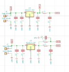
2. Should I separate DVCC and AVCC? If yes, I was thinking about these solutions:

In the first case, on top, is it better to have AVCC at the output of the regulator, or would
it be better to do the opposite?
Would the second solution be better?
Thanks for any hint.
Pastel
I'm not sure this is the proper place for that kind of question, so if it's not,
@moderators: please feel free to move this post.
I have made my first FPGA design. I'm using a MAX10 board and an extension on which
I have set a DAC (MAX5875).
For the moment, all my design does is generating a sine wave from an array (everything
is explained in the FPGA section).
Now what happens is that the SN ratio is quite poor. I get around 70 dB.
As the DAC is 16 bit, it's 96 dB on paper, and according to the datasheet, it should
be greater than 80 dB SFRD. So maybe it's the proper time to design a new PCB.
What I did (it's my first DAC hardware) is putting all grounds together, all
power lines together (of course the 1.8 and 3.3 are separated).
Now is it better to separate grounds? I have read contradictory stories about this,
and some are saying that a solid ground plane is better.
I made a 4 layers PCB. Front, L2, L3, Back. L2 is only ground. L3 is only power,
+5V, +3V3 and +1.8 V in the proper areas.
So here are my questions:
1. Should I separate grounds? (It might be a little bit tricky, I have more than 1 DAC,
so the story of 1 single contact point between AGND and DGND is not easy, there would
be islands of DGND and other islands of AGND. Ok, having a single point, then thick
lines leaving from there is possible. Another solution would be to add one AGND plane.
Would this make sense?
2. Should I separate DVCC and AVCC? If yes, I was thinking about these solutions:

In the first case, on top, is it better to have AVCC at the output of the regulator, or would
it be better to do the opposite?
Would the second solution be better?
Thanks for any hint.
Pastel
Last edited:


