Vermes
Advanced Member level 4

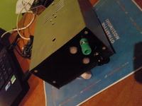
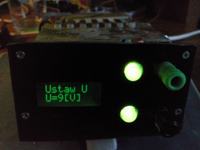
It is a small laboratory power supply. Eventually, it is to be helpful in the power of simple systems, mostly based on microprocessors. That is why the power supply has only one power circuit.
The PSU is made of LM317 and MJE2955 transistor. The system works in a typical catalog application. The device is powered from a transformer where U~19V (rectified), I~1,5A.
The device is controlled by an electronic switch (BCD to decimal code) “7442”. The switch after administration of the appropriate value for the input, gives the low state for a given terminal number. At this point, chose appropriate resistor values, which then set the appropriate voltage of the stabilizer output.
The main element of the power supply is Atmega8, clocked with an internal clock 8MHz. It controls the LCD display 8*2, two buttons with their backlight in two colors and mentioned before 7442 switch.
There is also a possibility to add a resistor 10ohm at the output of the power supply. It can be useful when you are not sure of an examined circuit (the power supply has no current limiter) and you do not want to burn it.
Possible power supply settings are: 3; 5; 7,5; 9; 10; 12; 14; 18 V.
The program was written in a way to prevent accidental turning on or changing the power.
When working, there are displayed some information about the voltage and current flow in the powered circuit.
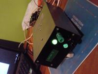
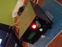
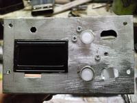
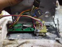
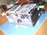
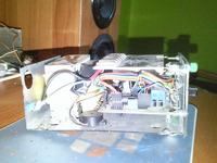

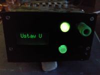
Link to original thread (useful attachment) – Mały zasilacz sterowany mikroprocesorowo.