rickyjar
Member level 2

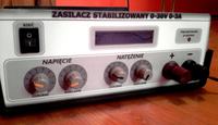
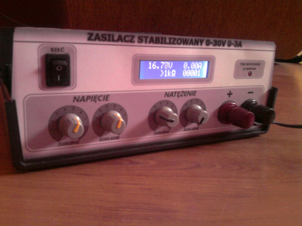
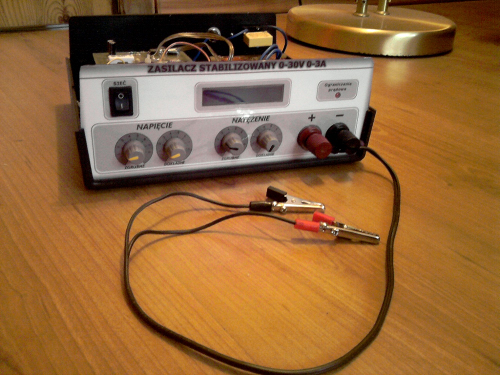
User K-3 presents his latest project “a power supply for an electronics engineer".
The project includes:
* A high-quality stabilised laboratory power supply with a continuously variable output voltage adjustable from 0-30V and output current limiter 2mA-3A, with an anti-short-circuit/anti-overload protection. This device is perfectly known to the circle of users at electronics-lab.
* A multimeter displaying voltage, current, resistance/conductance and amount of mAh transmitted to the load (useful while charging batteries), created with the use of the AtMega8, microprocessor, LCD display, 2x16 characters and SMD components. It’s equally famous project from the elfly portal.
Assumption:
To construct a relatively inexpensive, decent power supply that can be used successfully in the future.
Realization:
The user relied on the original projects from the above-mentioned links.
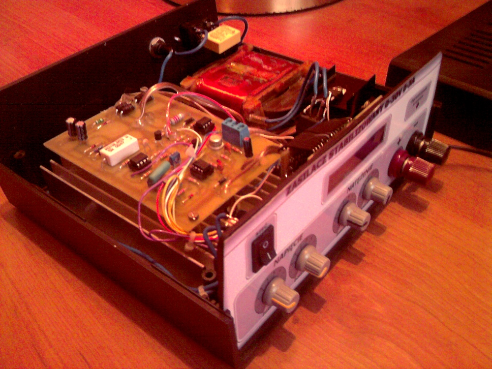
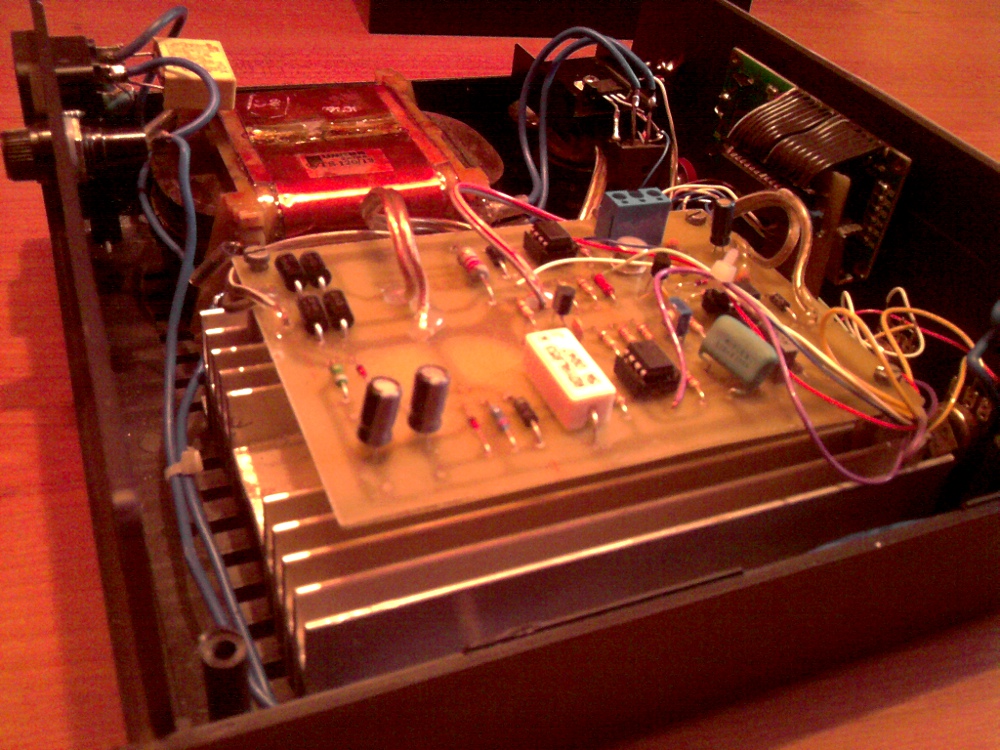
* The boards were etched using the thermotransfer method, after soldering, they were secured with a solution of rosin and denatured alcohol, thanks to which pathways will not oxidize.
* The front panel was designed by the user that was influenced a little bit by the projects of others users.
* A Unitra TS120/13 transformer was used (2x25,6V-2x2,2A ; 2x18,5V-2x0,15A; 120VA)
* KENDEIL 2x4700uF/63V capacitors filter voltage.
* Two 1kOhm potentiometers were added to regulate precisely voltage and current.
* A 2N3055 transistor was mounted on a very big heat sink, thanks to which a cooling fan does not have to be used (A whirring fan decreases comfort during work with the device).
Gallery:
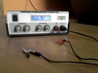
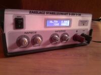
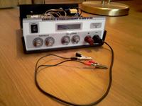
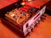
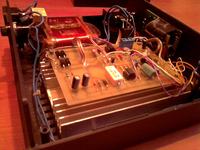
Construction time: about 2 weeks
Expenses: 200 PLN
The assumption was fulfilled: the user makes successful use of the power pack at its workshop.
The user recommends everyone interested to assemble such a device on their own. It is indispensable at any electronics engineer’s workshop, and knowledge, which one will gain, is priceless. In the event of any problems with constructing the power supply, the user is willing to offer his support.
Link to original thread - "Zasilacz dla elektronika"
Last edited:


