Vermes
Advanced Member level 4

Assumptions:
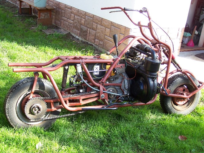
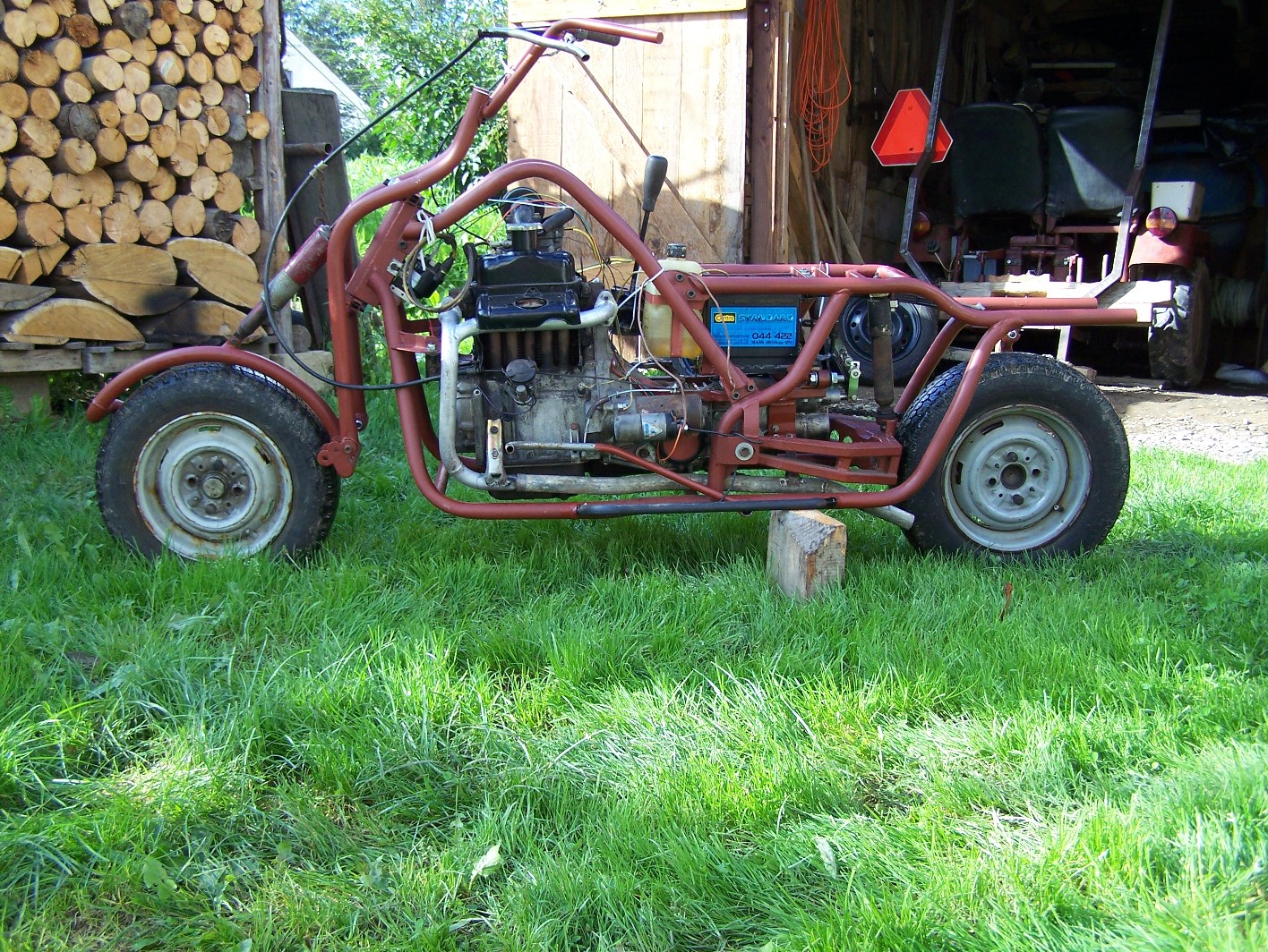
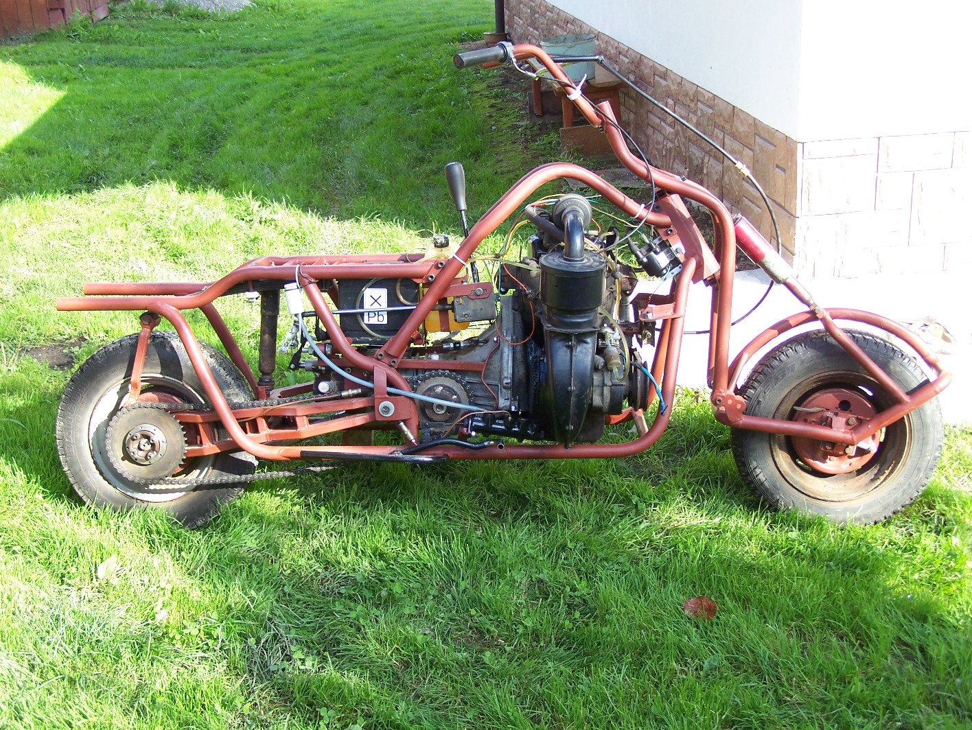
Firstly, to built a buggy – motorcycle on low costs and a minimal equipment needs. To make this, it was necessary to find a dead car Fiat 126p and use its elements. To make ride more comfortable, the hinges are placed in front and back side of the vehicle. The device can be used in a wild area and on roads.
Useful tools are: a hack saw, a grinder, a welder, a hand drill, metal file set , wrenches, a pipe bender, a vice, hammers, a tape measure, a pencil, clamps, a plaster patch to the equation.
Based on supplied pictures a turner made the mounting of the rear and front racks, rolle transfers to the gearbox, head frame, fork axis, the ends of shafts were welded to the shelf of the fork.
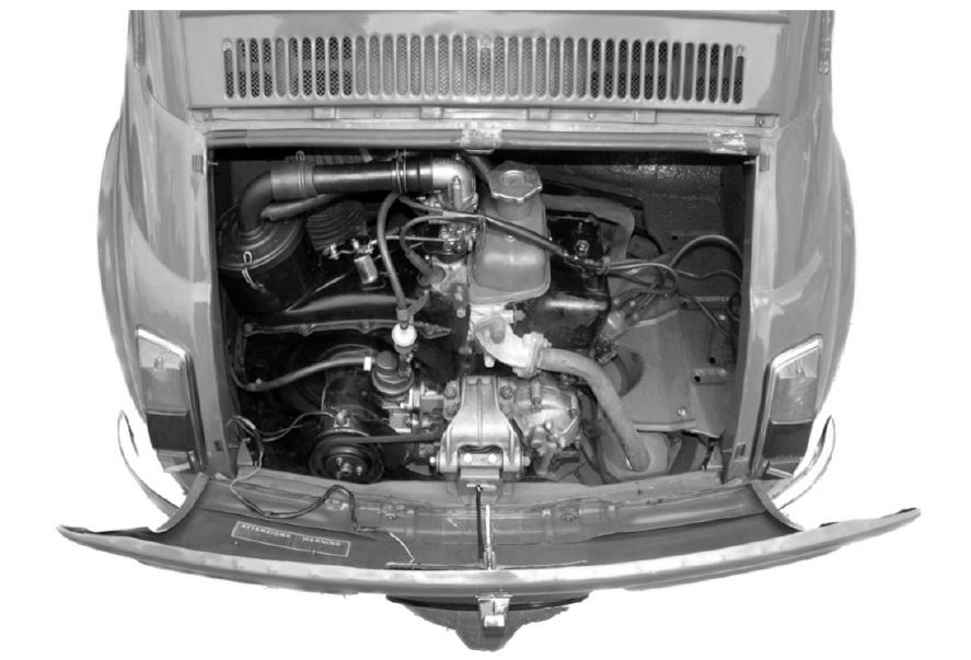
(photography from A.Sowy “Fiat 126p mały wielki samochód”)
Wheels 12'' from Fiat 126p
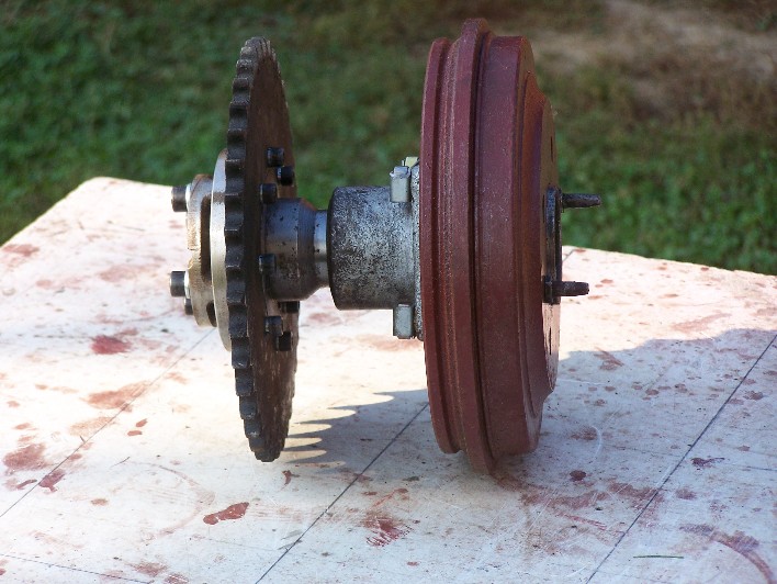
Left rear hub with rack mount.
Hydraulic brake on the front cylinder (larger diameter) and a pump depleted to only one section.
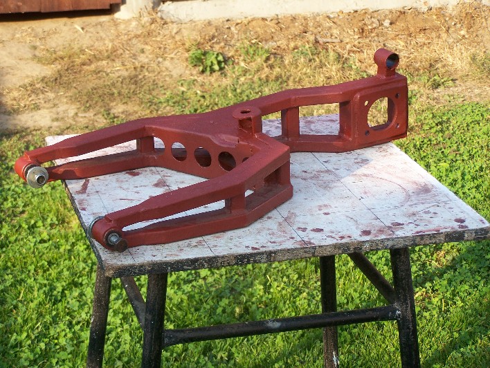
The rear dragged swingarm (made of 20x20 profile). Suspension on the front half of the trailing and additional adapter.
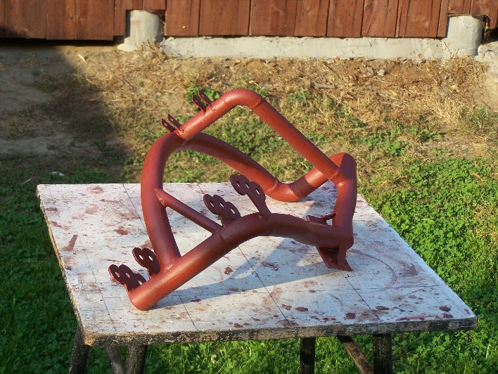
The frame of 1'' seamless pipe. Corrosion protection of primer-colored.
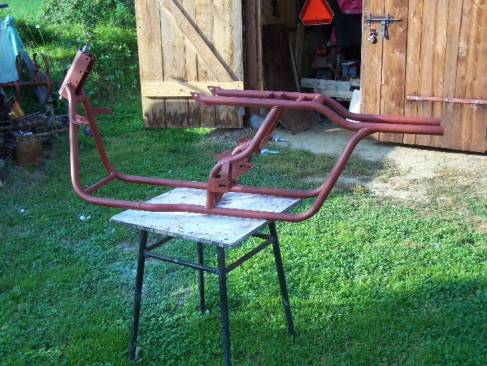
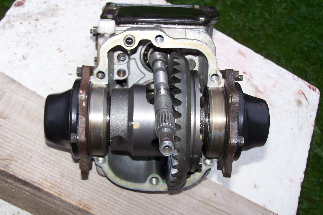
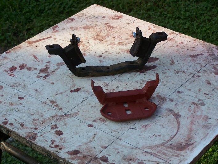
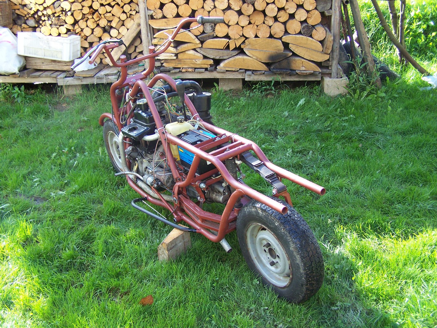
The top frame was spread for easy mounting of the engine. The gearbox is a serial one with some changes + the first one is suspension. Normally, the engine puts power through the torque and suspension on two cushions and a spring. Here the engine reflects the strength on the tension of the chain and after first immediately move that would be torn from its roots. A small frame was build for the gearbox.

The rear engine suspension made on silentblocks from front swingarm (from Fiat 126p) crammed to the bar bolted to the frame of the gearbox.
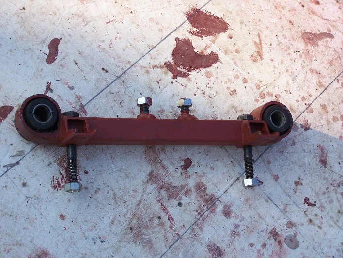
The M14 screws, which the siletblocks are loaded on let the engine move forward/backward to adjust chain tension. The second modification of the gearbox
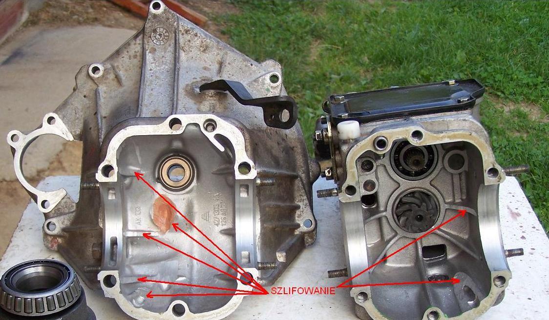
There was a hole in the housing of the clutch – it was plugged with a plate and some silicone. Next important thing is the sleeve and the shaft couplings. The sleeve catches on the crown wheel and therefore it must be sanded.
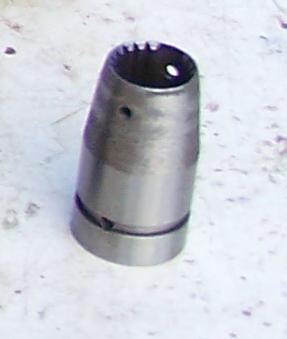
The shaft couplings also catches on the crown wheel and had to be grinded a little.
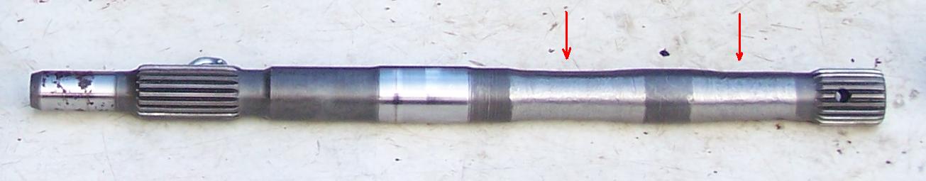
Then the sleeve was set up on the shaft, locked by a pin and the pin weld to the sleeve.
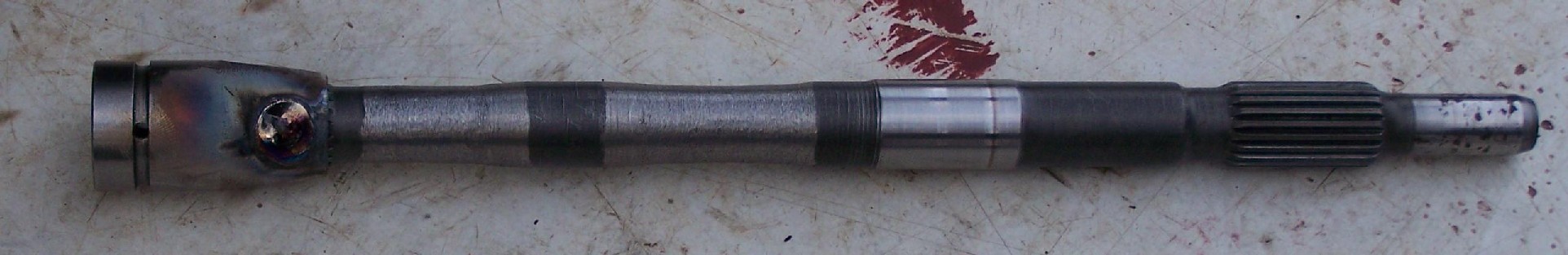
After removing the weld on the sleeve and getting a new roller, the gearbox could be made.
The engine has no major alternations, except of cutted thermostat cutted off, a cut off air intake and secure grid. The front engine mount is constructed from a serial chest suspension.
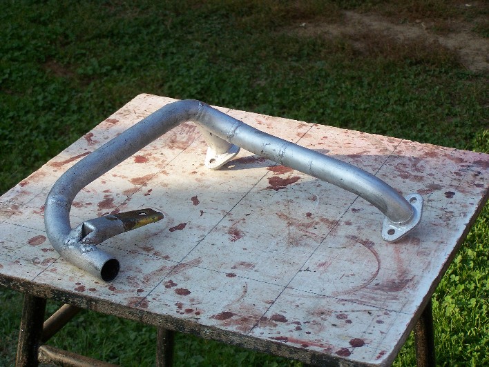
The exhaust manifold was stuck from a serial muffler by cutting the pipe to pieces, fitting and welding.
The head frame tube and two pieces of metal pipe carrying the load on the frame.
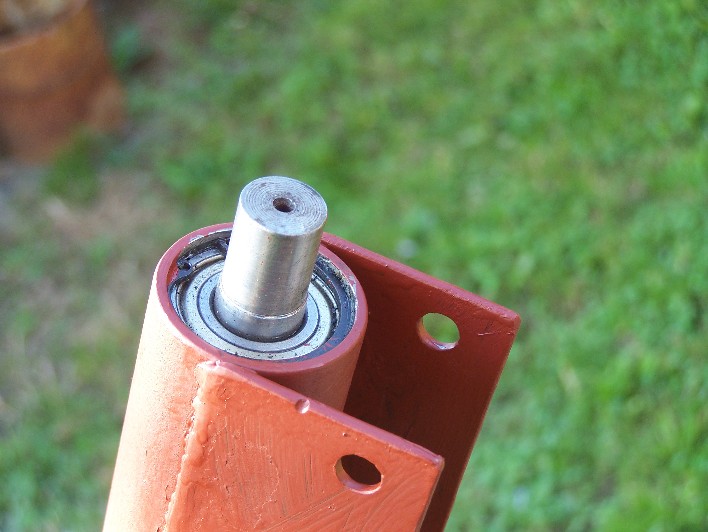
The pipe has two places for ball bearings.

The front swingarm is mounted on silentblocks.
Front hub is from Fiat 126p – weld to a new mount point. The hub is bolted with 3 screws to the swingarm, allowing to easily adjust the convergence.

The gears are changed as in Fiat 126p including backward gear.
The whole construction weights about 250kg.
The maximum speed – 60km/h.
Link to original thread - Motocykl z malucha czyli silnik 126p na dwóch kołach