infinite_gbps
Member level 3

So I wanted to just get a better understand on what I am looking it with this application note.
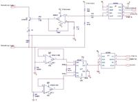
My question is, where is this 4-20 mA current coming from in this circuit. I know the current (they tell me if you click that link) that flows through R3 causes a voltage drop across R3 and this drop also appears RS but what is actually supplying this output "loop" current? The OpAmp?
Picture of App Note from Analog Devices:
https://www.analog.com/en/verifiedcircuits/CN0009/vc.html
**broken link removed**
Just a side question, when I Pspice this I could never get the non-inverting input of the OpAmp to be close to zero. It's always has some higher voltage like 2.5V compared to the inverting input that has nV.

