Continue to Site

Welcome to EDAboard.com

Welcome to our site! EDAboard.com is an international Electronics Discussion Forum focused on EDA software, circuits, schematics, books, theory, papers, asic, pld, 8051, DSP, Network, RF, Analog Design, PCB, Service Manuals... and a whole lot more! To participate you need to register. Registration is free. Click here to register now.

COMPIM and PROTEUS for PIC

Status
Not open for further replies.

nomad13

Full Member level 3
Full Member level 3
Joined
Jan 29, 2007
Messages
150
Helped
18
Reputation
36
Reaction score
6
Trophy points
1,298
Activity points
2,196
compim

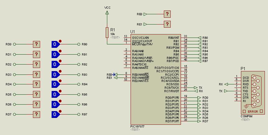
I tried to use compim feature of proteus to communicate to a GSM module. I use a 16F877 pic, the tx and rx are directly connected to a compim.

I send data to a compim but I receive unknown data on the other end.

What do I need to do?

I tried to use max232 on the circuit but I don't recieve any on the reciever end.

Can someone attach a board layout using a pic and a compim in proteus.

Thanks
 

compim proteus

I tried to use compim feature of proteus to communicate to a GSM module. I use a 16F877 pic, the tx and rx are directly connected to a compim.
16F877 Tx to COMPIM Tx. 16F877 Rx to COMPIM Rx

I send data to a compim but I receive unknown data on the other end.

What do I need to do?
COMPIM has communication parameter setting, you have to set it up.

I tried to use max232 on the circuit but I don't recieve any on the reciever end.
COMPIM has MAX232 already, don't add more.
 
proteus compim

Thanks for the info.

I already figured it out.

The problem was not from proteus but from proton picbasic.

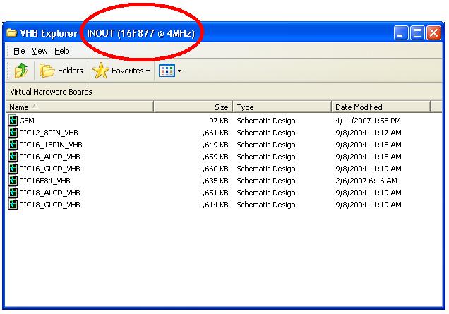
After pressing compile and program button (program thru proteus). On choosing the board the default crystal frequency was 4MHZ while on the program I am using 20MHZ. I still need to modify the crystal frequency before simulation. Is it possible to change the default frequency?

1_1176272081.jpg


61_1176271803.jpg
 

compin +proteus+gsm modem
Regards

i am using proteus to simulate my project that has an avr microcontroller controlling relays ,the avr is interfaced or attached to the gsm modem sim900d , call on gsm modem from stored number would activate the relay for a short period of time..
now i am using the compim to attach the modem to the simulation

i can read sms , extract the number and message..
but the problem is whenever there is a call on the number the RI pin 9 of compim is set, and i also see blinking on RX pin ,but no message is displayed on the VTERM, instead the the RI line hangs up set only and no further response is available from the modem, i am using the development kit from simcom,

i would attach the proteus pics after recieving call theere is no ring and +clip on rx terminal and RI is all time red

51214d1291211404-untitled-png
 

this is my coding which should send some data ..i have tried in proteus but no response..what is my mistake..


Code C - [expand]
1
2
3
4
5
6
7
8
9
10
11
12
13
14
15
16
17
18
19
20
21
22
23
24
25
26
27
28
29
30
31
32
33
34
35
36
37
38
39
40
41
42
43
44
45
46
47
48
49
50
51
52
53
54
55
56
57
58
59
60
61
62
63
64
65
66
67
68
69
70
71
72
73
74
75
76
77
78
79
80
81
82
83
84
85
86
87
88
89
90
91
#include <mega32.h>
#include <delay.h>
#include <stdlib.h>
 
#define red_1 PORTA.0
#define yellow_1 PORTA.1
#define green_1 PORTA.2
 
#define RXB8 1 
#define TXB8 0 
#define USBS      3
#define RXEN      4
#define TXEN      3
#define UCSZ1     2
#define UDRE      5
#define UCSZ0     1
#define RXC       7
 
 
void USART_Init(unsigned short int F_CPU_MHz, unsigned short int Baud_Rate)
{
   
    UCSRB = 0x00;                                         // Disable while setting baud rate
    UCSRA = 0x00;                                        // Disable USART flags
    UCSRC = (1<<USBS)|(1<<UCSZ1)|(1<<UCSZ0);        // 8-Bit data, 1-Bit Stop
    UBRRL = ((F_CPU_MHz*1000000)/Baud_Rate/16)-1;        // Set Baud Rate Lo - Asynch Normal Mode
    UBRRH = 0x00;                                         // Set Baud Rate Hi
    UCSRB = (1<<RXEN)|(1<<TXEN);                    // Enable USART TX and RX
}
 
 
void Send_Byte(char data)
{
 
    while ((UCSRA & (1<<UDRE)) == 0);
    UDR = data;
}
 
 
char Receive_Byte(void)
{
 
    while((UCSRA&(1<<RXC)) == 0);
    return UDR;
}


void main(void){
USART_Init(8,9600);
PORTA=0x00;
DDRA=0xFF;
PORTB=0x00;
DDRB=0x03;
PORTC=0x00;
DDRC=0xFF;
PORTD=0x00;
DDRD=0xFF;
 
while (1)
{ 
red_1=0; 
green_1=1;
delay_ms(1500);
green_1=0;
yellow_1=1;
delay_ms(1500);
yellow_1=0;
red_1=1;
delay_ms(1500);
};
 
while(1)
{
if (red_1==0)
    {
    green_1=1;
    Send_Byte('G');
    }
 
if (yellow_1==0)
    {
    red_1=1;
    Send_Byte('R');
     }}
     }


Last edited by a moderator:

Status
Not open for further replies.

Similar threads

Part and Inventory Search

Welcome to EDABoard.com

Sponsor

Back
Top