Continue to Site

Welcome to EDAboard.com

Welcome to our site! EDAboard.com is an international Electronics Discussion Forum focused on EDA software, circuits, schematics, books, theory, papers, asic, pld, 8051, DSP, Network, RF, Analog Design, PCB, Service Manuals... and a whole lot more! To participate you need to register. Registration is free. Click here to register now.

90 degrees phase shifter circuit

Status
Not open for further replies.

moeen

Newbie level 6
Newbie level 6
Joined
Mar 9, 2009
Messages
13
Helped
1
Reputation
2
Reaction score
1
Trophy points
1,283
Activity points
1,378
hello all ,
please I need to design 90 degrees phase shift circuit for a sine wave input , but the amplitude of output nearly the same amplitude of input signal , Please i need the typical circuit of these specification .
 

phase shifter.JPG

This should be of some help to you
 

Thanks a lot jeffrey samuel , but i need that using an Op-amp such as LM471 ???!!! ,,,,, I don't know if that possible or no !!!!!
 

A 741 cannot do this alone. It can invert which is almost the same as 180 shift but not any other angle. The trouble with phase shifting is the amount of shift depends on frequency so wideband circuts are difficult to build.
The "polyphase" network shown earlier is probably the best you will find. You can use a 741 to produce the anti-phase input the network requires and to buffer the outputs.

Brian.
 

A 741 cannot do this alone. It can invert which is almost the same as 180 shift but not any other angle. The trouble with phase shifting is the amount of shift depends on frequency so wideband circuts are difficult to build.
The "polyphase" network shown earlier is probably the best you will find. You can use a 741 to produce the anti-phase input the network requires and to buffer the outputs.
Nothing has been said about a frequency range in the original post. Thus I would suggest an active all-pass circuit. It can be easily adjusted to achieve 90° for a given frequency by varying a single resistor. https://en.wikipedia.org/wiki/All-pass_filter
 

Thanks all for replay , I would the circuit work at specific frequency " the frequency is fixed not variable " ,,,,,, general circuit design with there equation to complete my design ,,,,that's what i need ????
 

general circuit design with there equation to complete my design ,,,,that's what i need ????
It's all in the wikipedia link.
 

firstly thanks for your replay :) ,,,,,,,, but in the wikipedia link the phase shift circuit was -90 degrees phase shift at output as in attached picture ,,,,,,,,, and this mean i need second phase shift ???!!! ,,,,,,,,,,,, I need to enter sine wave to give me at output cosine wave , thanks .View attachment input Vs output.bmp
 

There was a thread here last May with a similar request.

Someone suggested a promising method built around an LC tank, which yields exactly 90 degrees phase shift due to resonating action.

Based on that, I managed to devise a circuit which appeared to work, although values have to be adjusted for a desired frequency range.

A bit of searching will locate the thread.

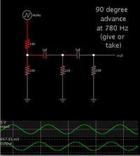
Or this method may suit. Two capacitors with a resistor network.


Values need to be adjusted for the desired incoming frequency.

The above example is for 780 Hz. Phase shift appears very close to 90 degrees down to 600 Hz and up to 1000 Hz.

The output will need to be amplified.
 

firstly thanks for your replay :) ,,,,,,,, but in the wikipedia link the phase shift circuit was -90 degrees phase shift at output as in attached picture ,,,,,,,,, and this mean i need second phase shift ???!!! ,,,,,,,,,,,, I need to enter sine wave to give me at output cosine wave , thanks .View attachment 81460
The phase shift in the Wikipedia circuit is +90 degrees, not -90 degrees, at the RC corner frequency. If you need the opposite phase shift, just interchange R and C.
 
  • Like
Reactions: FvM

    FvM

    Points: 2
    Helpful Answer Positive Rating
firstly thanks for your replay :) ,,,,,,,, but in the wikipedia link the phase shift circuit was -90 degrees phase shift at output as in attached picture ,,,,,,,,, and this mean i need second phase shift ???!!! ,,,,,,,,,,,, I need to enter sine wave to give me at output cosine wave , thanks .View attachment 81460

Why not simply use an inverting Miller integrator? I think it will introduce a phase error that is considerably lower if compared with all the other methods (due to parts tolerances).
 

The output will need to be amplified.

ahaaa ,,,,,,,,,,,, Thanks a lot for replay , but the phase shifter is one of a large circuit diagram ,,,,,, and i must to minimize the ICs and circuits as i can ,,,,,, thanks a lot :)

- - - Updated - - -

The phase shift in the Wikipedia circuit is +90 degrees, not -90 degrees, at the RC corner frequency. If you need the opposite phase shift, just interchange R and C.

I simulated it in many program and gives the same result -90 degree phase shift , and if i interchanged R & C gives incorrect result ,,,,,,,, thanks for your time :)

- - - Updated - - -

Why not simply use an inverting Miller integrator? I think it will introduce a phase error that is considerably lower if compared with all the other methods (due to parts tolerances).

Integrator change the amplitude of input signal according to frequency ,,,,,,,,,,,,, Thanks for your replay :)
 

Integrator change the amplitude of input signal according to frequency ,,,,,,,,,,,,, Thanks for your replay :)

Yes, that´s true. However, I was of the opinion that you need the phase shifter for one single frequency only.
On the other hand, an allpass provides the 90 deg also for one frequency only.
Therefore: What do you really need? A 90 deg phase shift with a constant amplitude for a certain frequency band ?
 

I simulated it in many program and gives the same result -90 degree phase shift , and if i interchanged R & C gives incorrect result ,,,,,,,, thanks for your time :)
Don't know what you are talking about. What is "incorrect result"? What would be the correct result?
 

What do you really need? A 90 deg phase shift with a constant amplitude for a certain frequency band ?

yes this which i need A 90 deg phase shift with a constant amplitude for a certain frequency band ,,,,,,,,, thanks :)

- - - Updated - - -

Don't know what you are talking about. What is "incorrect result"? What would be the correct result?


I mean that gives no phase shift as in picture

View attachment output1.bmp

and the correct result which i need it is A +90 degrees phase shift with a constant amplitude at certain frequency ,,,,,,,,,,, thanks a lot :)
 

yes this which i need A 90 deg phase shift with a constant amplitude for a certain frequency band ,,,,,,,,, thanks :)

- - - Updated - - -

and the correct result which i need it is A +90 degrees phase shift with a constant amplitude at certain frequency ,,,,,,,,,,, thanks a lot :)

In your own interest, you should try to describe your problem without such contradictions.
 

I mean that gives no phase shift as in picture.
I wonder how you read a phase shift from a single waveform? You possibly know the input waveform, but we don't.

P.S.: Guessing a bit about the missing information, it seems like the input waveform is a sine with 0 degree phase shift, switched on at t=0, and the output is a cosine. You have been possibly confused by the initial transient and missed to measure the actual phase shift.
 
Last edited:

In your own interest, you should try to describe your problem without such contradictions.

where are the contradictions ??!!!! ,,,,,,,,,,, i need phase shifter circuit with output amplitude as the same amplitude of input signal

- - - Updated - - -

I wonder how you read a phase shift from a single waveform? You possibly know the input waveform, but we don't.

P.S.: Guessing a bit about the missing information, it seems like the input waveform is a sine with 0 degree phase shift, switched on at t=0, and the output is a cosine. You have been possibly confused by the initial transient and missed to measure the actual phase shift.

ahha ,,,,, the input wave form is sine wave and I mean the exchange between R and C gives not exactly phase shift which I need ,,,,,,,,,, Thanks for your replay :)
 

ahha ,,,,, the input wave form is sine wave and I mean the exchange between R and C gives not exactly phase shift which I need
As a matter of fact, by exchanging R and C, the discussed allpass circuit covers a full phase range of 0..360 degree. Thus I wonder how you managed not to get the intended phase shift. I guess, either your circuit is wrong or you misunderstood the results.

 
  • Like
Reactions: moeen

    moeen

    Points: 2
    Helpful Answer Positive Rating
As a matter of fact, by exchanging R and C, the discussed allpass circuit covers a full phase range of 0..360 degree. Thus I wonder how you managed not to get the intended phase shift. I guess, either your circuit is wrong or you misunderstood the results.

OK Thanks for your replay ,,,, now i found PDF file in the link give me the design ,,,,,,,,,,, ThanKs a lot for your time :))
 
  • Like
Reactions: zeefah

    zeefah

    Points: 2
    Helpful Answer Positive Rating
Status
Not open for further replies.

Similar threads

Part and Inventory Search

Welcome to EDABoard.com

Sponsor

Back
Top