Continue to Site

Welcome to EDAboard.com

Welcome to our site! EDAboard.com is an international Electronics Discussion Forum focused on EDA software, circuits, schematics, books, theory, papers, asic, pld, 8051, DSP, Network, RF, Analog Design, PCB, Service Manuals... and a whole lot more! To participate you need to register. Registration is free. Click here to register now.

90 degree traces routing

Status
Not open for further replies.

karthik2dave

Newbie level 5
Newbie level 5
Joined
Mar 23, 2015
Messages
8
Helped
0
Reputation
0
Reaction score
0
Trophy points
1
Activity points
68
anybody know how to find 90 degree traces in pcb soft wares once finished routing... like as allegro, pads layout etc... if any found script please provide
 

Why they don't cause any problems....
But if you have to then visually......
 

Traces routed in 90 degrees are not well suited to work at much higher frequencies, however RF stages in PCBs are in general confined to a small region of the board, becoming easy to find it.
 

I wouldn't use them for RF but for std digital you can go into the GHz I believe
 

If routed with a round D code, the outside corner should be smooth with same diameter.
If routed with a square D code, the corner will be sharp and produce higher e-field leakage due to sharp gradient but only significant at UHF + to nearby traces.

It may also affect S parameters slightly for Controlled impedance with change in width and more likely above 2GHz.

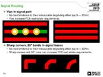
high-speed-and-rf-design-considerations-ve2013-45-638.jpg
high-speed-and-rf-design-considerations

A script program could written to count the 90 deg bends but not usually found in typical CAD files.
 

You don't route with a D code, that is down to the plotting, and you NEVER draw with a square D-code ever, even when we had to put the apertures in the aperture wheel we never used a square aperture.
There are many papers and comments on 90 degree corners including Howard Johnsons view, I don't use them because I don't think the boards look pretty enough when they are used, but have done to prove a point and don't worry if one or two appear on a board.
Then if your signal goes through a via the it travels through 2 right angled bends.....
 

Chaps, your veering towards another discussion - the OP only asked how to find them.
 

It is possible to create a simple program in some high level language ( e.g Java ) that opens the output ASCII generated Gerber text file to seek for orthogonal coordinates at subsequent positions. In other words, if some two consecutive track are defined as
  • <Pi ,Pi+1> = <(XiYi),(Xi+1Yi+1)>
  • <Pi+1 ,Pi+2> = <(Xi+1Yi+1),(Xi+2Yi+2)>

We can assume that both tracks have a 90 degree rotation either if :
  • Xi=Yi+1 and Yi+1=Xi+2 or
  • Yi=Xi+1 and Xi+1=Yi+2

With a simple string manipulation, this should be not too difficult to scan the entire board. Knowing that the standard EIA RS-274 pattern that defines traces is something like formatted bellow:
Code:
X0000000Y0000000…
X1111111Y1111111…
X1111111Y2222222…
X2222222Y2222222…
X2222222Y1111111…
Therefore, at the above sample we can note that the angle at the corner between traces <(111111,11111),(11111,22222)> and <(222222,22222),(22222,11111)> is orthogonal. The only remark on this approach is that such technique do not provide a friendly way to graphically interface with the user, being necessary a further interaction with the original CAD to find the matching corner.
 

Attachments

  • PCB.png
    PCB.png
    9.7 KB · Views: 99

You don't route with a D code, that is down to the plotting, and you NEVER draw with a square D-code ever, even when we had to put the apertures in the aperture wheel we never used a square aperture.
There are many papers and comments on 90 degree corners including Howard Johnsons view, I don't use them because I don't think the boards look pretty enough when they are used, but have done to prove a point and don't worry if one or two appear on a board.
Then if your signal goes through a via the it travels through 2 right angled bends.....

THat's what I Meant !

When Gerber File is created, the routing is done with round D-codes as selected by trace width in layout package.

Did you see my report link? https://image.slidesharecdn.com/ve1...onsiderations-ve2013-45-638.jpg?cb=1379322252
 

Yes but Gerber never draws with a square aperture, only round apertures are used for draws. Round and square and any other shape can be used for flashes (pads etc.). I was referring to your comment about routes done with a square aperture.
 

It is possible to create a simple program in some high level language ( e.g Java ) that opens the output ASCII generated Gerber text file to seek for orthogonal coordinates at subsequent positions. In other words, if some two consecutive track are defined as
  • <Pi ,Pi+1> = <(XiYi),(Xi+1Yi+1)>
  • <Pi+1 ,Pi+2> = <(Xi+1Yi+1),(Xi+2Yi+2)>

We can assume that both tracks have a 90 degree rotation either if :
  • Xi=Yi+1 and Yi+1=Xi+2 or
  • Yi=Xi+1 and Xi+1=Yi+2

With a simple string manipulation, this should be not too difficult to scan the entire board. Knowing that the standard EIA RS-274 pattern that defines traces is something like formatted bellow:
Code:
X0000000Y0000000…
X1111111Y1111111…
X1111111Y2222222…
X2222222Y2222222…
X2222222Y1111111…
Therefore, at the above sample we can note that the angle at the corner between traces <(111111,11111),(11111,22222)> and <(222222,22222),(22222,11111)> is orthogonal. The only remark on this approach is that such technique do not provide a friendly way to graphically interface with the user, being necessary a further interaction with the original CAD to find the matching corner.


Great~!!

And Allegro PCB has a scripting language : SKILL

Does anyone know how to find improper PCB design by means of this ?

e.g. 90 degree corner, critical signal via that is not surrounded by GND, the RF trace that is overlapped by power trace...

Thanks a lot~!!
 

90 degree corners aren't improper...
As to the rest, simple don't design in the errors when you are laying out a board, that's what I do and then I check my design closely... that's why us humans are better than computers at doing this sort of thing...
So good design practice and good checking procedure to capture any faux pas in the design stage...
 

Some tools have already ways to define default routing style, as for instance the Altium uses the 45 degrees as standard pattern ( see page 34 of this document ). I'm not sure whether this configuration is seen by software as preferred or mandatory. Anyway, apart from how much 90 degrees could affect the signal integrity, I think that soft angles give a better visual aspect to the layout design, but it is just my opinion.
 

They do and take less space, I always use them, if for no other reason to avoid electronics engineers crying and whining:-D

Also can look prettier with 45s... Once did a board with all 90 degree angles to see if it made any difference wots so ever and it didn't (the board ended up as part of the control circuitry for the magnets at Daresbury Nuclear Physics Laboratory ring....
 

The only type of signals that I usually do not perform routing with 45 degrees are the DC power buses. If you asked me what is the science behind it, I could not answer with a plausible justification, but each madman has his own madness.
 

As said I always use 45 degree traces, even into the corners of SMD pads... (that would be another interesting thread) because the end results look nice and even though it doesn't matter electronically I like to see signal traces as smoothly routed as possible with the minimum number of segments, the design has to look like its flows (no nasty staircase routing)... its probably also an old school thing from learning by doing tape ups, you developed a style that minimised tape cuts and corners.
I think we are also pr-programed to view 45 routes as normal and find 90 routes strange, yet if you look at routing in ICs they tend to be more 90 degree (though there was a patent issued for 45 degree IC routing a few years ago...)>
Still working on a list:)
 

A right angle bend creates additional capacitance and there will be slight amount of capacitive reflection. However, this reflection is of the order of less than 0.05 pf and can be ignored in most cases. The calculation at http://referencedesigner.com/books/si/ch16_5.php shows that the additional capacitance is of the order of 0.01 pf.

I will be more concerned about the capacitive discontinuity due to via.
 

anybody know how to find 90 degree traces in pcb soft wares once finished routing... like as allegro, pads layout etc... if any found script please provide

I believe that if you run glossing in Allegro it will remove the 90 degree traces not positive though. It is best not to route with 90s. They cause reflections, impedance issues etc.

Erik
eLab Electronics
www.elabelectronics.com
 

A sharp point only increases the field intensity making the field strength radiate a much stronger at that point, which is bad for close track crosstalk. It's not the capacitance change.

The capacitance change is almost null, but the capacitance is unlikely to cause signal distortion from 50 OHm CMOS drivers unless the path length exceeds 10% of a wavelength for the rise time related maximum bandwidth.

However for microwave it changes the trace width over ground and will cause reflections from the impedance drop at that point and a degradation in return loss.
 
This may be true but as Howard Johnson and many others have said it don't matter until you get to microwave, it is also NEVER a sharp point but always has a radius
 

Status
Not open for further replies.

Part and Inventory Search

Welcome to EDABoard.com

Sponsor

Back
Top