FenTrac
Full Member level 5

- Joined
- Jul 6, 2014
- Messages
- 248
- Helped
- 50
- Reputation
- 102
- Reaction score
- 54
- Trophy points
- 1,308
- Location
- West Coast
- Activity points
- 4,264
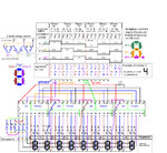
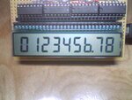
This project uses a glass 9 Digit 7 Segment Multiplexed LCD with 30 pins,
driven by 4 74HC595 shift registers, so that a microcontroller can run it
using 3 output pins.
The display has 3 backplanes , 9 digits, and 8 decimal points. It was
probably designed for a frequency counter or some other application that
only required digits and decimal points.The resistor network generates
3 backplane voltage levels.
The backplane signals need 6 clock phases, at three voltage levels,
5v, 2,5v, 0v. The backplane signals are shifted by 1 phase clock from each
other. A 6 resistor voltage divider network generates the 3 voltage levels
from the 2 level shift registers outputs.
The 27 segment pins, 3 for each digit, are driven with 2 voltage levels,
0 and 5 volts.
Three interface pins from a microcontroller provide the shift register's
clock, data, and latch input. to drive the display. All of the logic to
drive the display is generated by software. Segments can be controlled
individually, so some letters and symbols are possible as well as numbers.
For example: A C E F H I J L O P S U [ ] _ - = b c d h i l o u.

code example:

driven by 4 74HC595 shift registers, so that a microcontroller can run it
using 3 output pins.
The display has 3 backplanes , 9 digits, and 8 decimal points. It was
probably designed for a frequency counter or some other application that
only required digits and decimal points.The resistor network generates
3 backplane voltage levels.
The backplane signals need 6 clock phases, at three voltage levels,
5v, 2,5v, 0v. The backplane signals are shifted by 1 phase clock from each
other. A 6 resistor voltage divider network generates the 3 voltage levels
from the 2 level shift registers outputs.
The 27 segment pins, 3 for each digit, are driven with 2 voltage levels,
0 and 5 volts.
Three interface pins from a microcontroller provide the shift register's
clock, data, and latch input. to drive the display. All of the logic to
drive the display is generated by software. Segments can be controlled
individually, so some letters and symbols are possible as well as numbers.
For example: A C E F H I J L O P S U [ ] _ - = b c d h i l o u.

code example:
Code:
// PIC18F1550/4550
// 4 - 74HC595 shift registers, 9 digit LCD, 3 voltage level backplanes
// uses timer0 interrupt, PORTA pins 3,4,5

#include <xc.h>
#define _XTAL_FREQ 48e6

char dupdate = 0;
char bpclock = 0;
char phase = 0;
char cycles = 0;
char dec = 0;    // digit number for decimal point
char LCDdisplay[9] = {9,8,7,6,5,4,3,2,1}; // 9 digits to be displayed (in reverse order)
                                  //   s(10) = Space, c(11) = backplane Control levels
                                  //  0,1,2,3,4,5,6,7,8,9,s,c numeral segment bit definitions
const char segdefs[][12] = { {0,6,4,4,2,1,3,4,0,0,7,3},    // phase 0
                             {2,6,1,4,4,4,0,6,0,4,7,6},    // phase 1
                             {5,7,5,5,7,5,5,7,5,7,7,5} };  // phase 2

void setup();
void loop();
void phase_cycle();

void main()
{
    setup();

    while(1)
      loop();
}

void interrupt ISR()
{
   if(TMR0IE && TMR0IF) //Check for TMR0 Overflow interrupt
     {
     TMR0L = 0;   // writing TMR0L re-loads TMR0H to TMR0
     dupdate = 1; // tell loop() to clock out 30 bits to shift registers
     TMR0IF=0;    // Clear timer0 interrupt Flag
     }
}


void setup()
{
 int tmrd;
//Setup Timer0
   T0PS0=1;    //Prescaler is divide by 256 (111)
   T0PS1=1;
   T0PS2=1;

   PSA=0;      //Timer Clock Source is from Pre-scaler

   T0CS=0;     //Pre-scaler gets clock from FCPU (12MHz)

   T08BIT=0;   // timer 0 set to 16 bit mode = 0
                  // set timer0 to @10 ms  (1/fosc/4/256/512)
   TMR0H = 0xFE;  // load high and low bytes of TMR0 register
   TMR0L = 0x00;  // (needs to be done in this sequence)

   TMR0IE=1;   // Enable TIMER0 Interrupt
   PEIE=1;     // Enable Peripheral Interrupt
   GIE=1;      // Enable INTs globally

   TMR0ON=1;   // start timer0

   TRISB4 = 1; // bootloader sense (set as input)
   TRISA3 = 0; // SR latch clock (set as output)
   TRISA4 = 0; // SR data  (set as output)
   TRISA5 = 0; // SR clock (set as output)
}


void phase_cycle()
{
  char digit, group, segs, shift;

    for(group = 10, digit = 0; group > 0; group--, digit++ )  // shift out 10 groups of three bits = 1 line of 30 bits
       {
       if(group == 1)  // group 1 = pins 1,2,3, (the three backplanes)
          segs = segdefs[phase][11]; // read 3 backplane bits from clkno
       else
          segs = segdefs[phase][LCDdisplay[digit]]; // read 3 number segment bits from clkno
       if(phase == 2 && dec == digit)   // check dec for decimal point position
          segs = (segs & 0xFE);         // if match, clear decimal point bit = decimal point on
       if(bpclock > 2)
          segs = ~segs; // invert segment and backplane control levels for clocks 3,4,5

       for(shift = 3; shift > 0; shift--, segs = segs>>1)  // shift out 3 bits ( 1 digit )
          {                                                // and shift segs to next bit
          if((segs & 0x01) == 0)
            LATA4 = 0; // PORTA 4, data = 0
          else
            LATA4 = 1; // PORTA 4, data = 1
          LATA5 = 1;   // PORTA 5, shift clock HIGH
          LATA5 = 0;   // PORTA 5, shift clock LOW
          }
       }
    LATA5 = 1;   // PORTA 5, shift clock HIGH, (shift one more time)
    LATA5 = 0;   // PORTA 5, shift clock LOW
    LATA3 = 0;   // PORTA 3, latch clock LOW, (latch data to SR outputs)
    LATA3 = 1;   // PORTA 3, latch clock HIGH

    if(++bpclock > 5) // go to next line at next interrupt
       bpclock = 0;   // go back to clock 0 on next interrupt
    if(++phase > 2)   // keep phase clock 0, 1,or 2
       phase = 0;
    dupdate = 0;      // clear flag (to be set by next interrupt)
    cycles++;         // count interrupts for "counting display" timing
}


void loop()
{                // loop cycles through numbers and decimal points
  char j;

  if(dupdate == 1)   // flag for a phase change
    phase_cycle();  // go to next phase clock cycle

  if(cycles == 65)  // 65 interrupts between display[] counting
    {
    cycles = 0;    // reset interrupt cycles count to 0
    for(j = 0; j < 9; j++)   // count each digit up
      if(LCDdisplay[j]++ > 9)
        LCDdisplay[j] = 0;
    if(dec++ > 7)  // cycle decimal points through display
      dec = 0;
    }
}