Continue to Site

Welcome to EDAboard.com

Welcome to our site! EDAboard.com is an international Electronics Discussion Forum focused on EDA software, circuits, schematics, books, theory, papers, asic, pld, 8051, DSP, Network, RF, Analog Design, PCB, Service Manuals... and a whole lot more! To participate you need to register. Registration is free. Click here to register now.

74174 working/ and how to configure it acc. to your circuit

Status
Not open for further replies.

aliahsan951

Junior Member level 3
Joined
Aug 14, 2017
Messages
28
Helped
0
Reputation
0
Reaction score
0
Trophy points
1,281
Location
GB
Activity points
1,509
i am making a tic tac toe project using logic gates........ and there i have to use 74174.....? share your thoughts on how it works
 

Set up a circuit to mimic the 9 tici-tac-toe squares.
Each square can contain null or X or O. That makes 3 possibilities.
You must contrive a circuit to display what is each of the 9 squares. Press buttons which enter something in a square (either X or O).
Start a new game by sending a 'clear' to all gates.

Do you wish to build a circuit that is a tic-tac-toe opponent? That will require a lot of work.
 

i had the circuit from someone...... and i am not understanding why the 74174 is used
 

You may find it feasible to use different flip-flops. For instance, try to picture how you might build the project using plain SR latches (a simple 'memory' circuit made from two cross-biased transistors). With some comparison you may discover convenient advantages if you step up to JK type, or D type, or a single common clear pin, etc.

74174= D flip flop (several on one chip). I believe the purpose is to simplify your physical layout, so that it is easier to examine the flow of logic. Or easier to add complexity to your logic circuit. Perhaps features such as:
* Automatic detection of a 'winner'.
* Ensure a square is only filled one time.
 
oh i got it........ d flip flop has been used to save turns......... 74174 has been used to simplify the turn count (whether its 1st player turn or 2nd's turn) it has been used then its output is then given to d flip flops..... thanks..

i am working on circuit...... if i have any issues i would tell you........
 

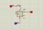
hey brother....... i have a problem.... while making tic tac...... i have used push buttons... they had a momentary required output...... so i have to save it for further usage..... for that i have used d-flip flop...... you can check the picture below.....
assdad.PNG

when i pushes button , it saves and gives output to Q...... now what should i do with rest of D,clk pins....should i connect to input... or should i neglect them..... and am i correct???
 

74xxx is old fashioned TTL that uses a high supply current all the time even when it is not doing anything. I stopped using TTL about 38 years ago and have used CD4xxx and 74HCxxx Cmos logic ICs ever since.
I would use an SN74HC174 to replace an old 74174.
 

74xxx is old fashioned TTL that uses a high supply current all the time even when it is not doing anything. I stopped using TTL about 38 years ago and have used CD4xxx and 74HCxxx Cmos logic ICs ever since.
I would use an SN74HC174 to replace an old 74174.

brother i am also using cmos version................ tell me my about reply post answer regarding d-flip flop ic
 

HI,

A general rule: "Don´t leave (unused) inputs floating."

The schematic in post#6 leaves
* D floating
* CLK floating
* S floating when the button is not pressed.

You need to give valid input levels. Either HIGH or LOW.

You need to clearely define your desired function. I recommend to read about some basic logic functions.
There are diagrams that show a function with a timing.
There are functional charts, like truth tables.
They make sense, because textual descriptions mostly are ambiguous.

***
About your circuit/function of post#6:
A SET function wihtout any RESET function makes no sense. You didn´t define when/how to RESET the output.

Klaus
 
now what should i do with rest of D,clk pins....should i connect to input...

You do not need to create a high-frequency clock. Experiment to find out which voltage to apply (high or low) to each terminals, so that the flip-flop works properly.

You should add a pullup (or pulldown) resistor to whichever terminal has the momentary switch.
 
i am making a tic tac toe game using digital logic. the players will input using push buttons. for this i have to save the inputs for further usage.. as push buttons has momentary output..... so for that i am using d-flip flop......now when i give output of push button to set of flip-flop, it saves the output.... reset (r) is normally grounded. when i need to reset.....i give it positive to
it (r). now what should i do with the remaining pins..

whether i give "0" to both d and clk or "1". the output remains save....

remembering that i am giving momentary output of push buttons to "s" of d-flip flop...... and it saves the input and gives it on "q"...... whether using "d" and "clk" or just ignoring them...

- - - Updated - - -

You do not need to create a high-frequency clock. Experiment to find out which voltage to apply (high or low) to each terminals, so that the flip-flop works properly.

You should add a pullup (or pulldown) resistor to whichever terminal has the momentary switch.

* flip flop is working properly in proteus software without giving any inputs {either "1" or "0"} to each terminals......
should i check and confirm it practically before pcb designing....


*and you had asked for a pull up or pull down resistor.......
this circuit is using almost 30 to 45 ICs.......(combining logic gates and flip flops) i am using 4 external voltage sources.......
now my question is which resistor value is appropriate for this circuit....

- - - Updated - - -

- - - Updated - - -

HI,

A general rule: "Don´t leave (unused) inputs floating."

The schematic in post#6 leaves
* D floating
* CLK floating
* S floating when the button is not pressed.

You need to give valid input levels. Either HIGH or LOW.

You need to clearely define your desired function. I recommend to read about some basic logic functions.
There are diagrams that show a function with a timing.
There are functional charts, like truth tables.
They make sense, because textual descriptions mostly are ambiguous.

***
About your circuit/function of post#6:
A SET function wihtout any RESET function makes no sense. You didn´t define when/how to RESET the output.

Klaus
i am making a tic tac toe game using digital logic. the players will input using push buttons. for this i have to save the inputs for further usage.. as push buttons has momentary output..... so for that i am using d-flip flop......now when i give output of push button to set of flip-flop, it saves the output.... reset (r) is normally grounded. when i need to reset.....i give it positive to
it (r). now what should i do with the remaining pins..

whether i give "0" to both d and clk or "1". the output remains save....

remembering that i am giving momentary output of push buttons to "s" of d-flip flop...... and it saves the input and gives it on "q"...... whether using "d" and "clk" or just ignoring them...
 

Hi,

flip flop is working properly in proteus software without giving any inputs
In a real circuit this will not work.
You may ask yourself if such a simulation tool is useful. On the other hand every designer should know that inputs shouldn´t be left floating.

pull up / pull down resistor:
Meaningless how many ICs you have. Just look into the datasheet for the one you want to use the pull up.
Read: V_IH, VIL, IIH, IIL. this gives you thel max limit of the resistor.
Usually 10k is a good value to start. For very noisy environment or lenghty traces use a lower value. To reduce supply current you may use higher value resistors.

Klaus
 
should i check and confirm it practically before pcb designing

Yes, it's essential that you experiment with hardware, to learn what quirks the real IC has, startup considerations, voltage range, etc.

this circuit is using almost 30 to 45 ICs.......(combining logic gates and flip flops) i am using 4 external voltage sources

I'll bet at least one student is using 9 IC's. Two ff per square. One ff lights a red led, another lights a green led. Call one X, call the other O. It's just a different approach.
 

I'll bet at least one student is using 9 IC's. Two ff per square. One ff lights a red led, another lights a green led. Call one X, call the other O. It's just a different approach.[/QUOTE]

i didn't understand what you want to say.......

- - - Updated - - -

I'll bet at least one student is using 9 IC's. Two ff per square. One ff lights a red led, another lights a green led. Call one X, call the other O. It's just a different approach.


i didn't get what you want to say
 

Hi,

i didn't get what you want to say
What exactly you don't understand?

***
I don't understand something in your posts:

You always talk about 74147.....it is a 6x DFF without SET and without RESET
But in post#6 you used a different gate. And here you use the SET input .... that you don't have in your 74147.

When you build the real circuit ... how do you overcome this problem?

Klaus
 

look brother i think i have confused you.... 74174 was to be used to set the turn for each player in game..... and i was not able to understand " how it would be possible ". then someone above replied to study the datasheet of 74174...... which i studied and got my answer..... that thing was solved..............

now i was having problem with using 4013 d-flip flop to save the output of push buttons from each player..... which was further to be utilized...... i was able to save the output.... but i don't know what to do with the remaining unused pins....... so i asked you...... someone replied to check it by applying positive and negative input practically .
 

You are mixing old fashioned high input current 74174 TTL with completely different CD4013 low output current Cmos.
A 0.5mA output low of a 4013 cannot drive a 1.6mA input of the 74174.
A 2.4V TTL high cannot make a 3.5V Cmos high.

You said you are using the Cmos version then why did you talk about the old TTL version, BROTHER? (I have a sister but not a brother)
i am using this one
cmos.PNG
 

i didn't understand what you want to say

There is more than one way you can design the logic for this project. It would help if you were to explore some of these methods, starting with the simplest. Example, draw an old-fashioned electrical version of this game using 18 ordinary bulbs and SPST switches. Its structure should give you an idea of what you need to achieve with momentary SPST switches controlling your flip-flops.
 
Status
Not open for further replies.

Part and Inventory Search

Welcome to EDABoard.com

Sponsor

Back
Top