Continue to Site

Welcome to EDAboard.com

Welcome to our site! EDAboard.com is an international Electronics Discussion Forum focused on EDA software, circuits, schematics, books, theory, papers, asic, pld, 8051, DSP, Network, RF, Analog Design, PCB, Service Manuals... and a whole lot more! To participate you need to register. Registration is free. Click here to register now.

7 seg. display an an FPGA board

Status
Not open for further replies.

keremcant

Member level 5
Member level 5
Joined
Dec 25, 2009
Messages
87
Helped
6
Reputation
12
Reaction score
5
Trophy points
1,288
Visit site
Activity points
1,910
hi,
I'm trying to use the 7 segment displays on a Digilent Basys FPGA board. it has four 7 segment displays combined together. every display has a different anode pin value but all the displays have the same cathode pin values. how can I choose the display I want to use? In the ucf file or in the verilog code?
 

The usual way of controlling multiple displays is by alternating which individual display is 'active'.

So, if you're looking to display 1234 on the four displays, you'd:
Turn on first display
Set outputs that match number 1 in 7-seg code
Turn off first display
Set outputs that match number 2 in 7-seg code
Turn on second display

and so on.

If you do this quick enough, it appears as if all four are lit at the same time..


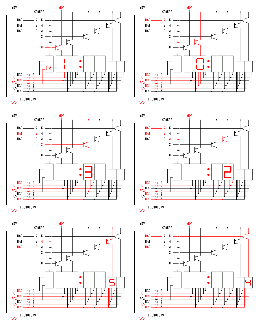
Found this awesome animation (courtesy of Seiichi Inoue) explaining exactly how it's suppose to work:

pic6_732.gif
 

okay but my question is actually how to turn on and off a display. I mean do I assign 0 on the anode and 1 on the pins of the cathode? or vice versa?

---------- Post added at 20:38 ---------- Previous post was at 20:34 ----------

for example in the animation it seems like both the anodes and the cathode pins are assigned 1, but shouldn't they be differently polarized?
 

The red ones are the ones that have current flowing through them, it doesn't mark which pins are on logic 1.
 

so could you give me a small example of how to do it? say I have the two anodes:
an1: P32, an0: P33; and the cathodes are P25, P16, P23, P21, P20, P17, P83 as in ABCDEFG.

how can I display, for example, 12 on the display? I mean how can I display 1 on the first one and 2 on the second one?

for example if I want to show only 1 on the first display, is it something like that:

Code:
reg[6:0] seven_seg_pins;
reg [1:0] anodes;

always@(posedge clock) begin
     anodes <= 2'b01;
     seven_seg_pins <= 7'b0110000;
end

Here what I am trying to show that should I assign opposite values to them to make the led shine?
 

Hi.
I've got the Basys2 development board from Digilent and started programming in VHDL about 2 weeks ago.
I made a couple of projects already, using the seven segment.
You can read about them, see a video and download the code at my blog: **broken link removed**

Best Regards
Thomas Jespersen
 

Status
Not open for further replies.

Similar threads

Part and Inventory Search

Welcome to EDABoard.com

Sponsor

Back
Top