Continue to Site

Welcome to EDAboard.com

Welcome to our site! EDAboard.com is an international Electronics Discussion Forum focused on EDA software, circuits, schematics, books, theory, papers, asic, pld, 8051, DSP, Network, RF, Analog Design, PCB, Service Manuals... and a whole lot more! To participate you need to register. Registration is free. Click here to register now.

[SOLVED] 600V/2A Diode with a very high VF of 9.07V. Anyone know what kind of diode this is?

Status
Not open for further replies.

lawcuenca

Junior Member level 3
Joined
Aug 5, 2010
Messages
25
Helped
1
Reputation
2
Reaction score
1
Trophy points
1,283
Activity points
1,450
Hi All,
I am looking for a diode with the subject ratings. I have encountered many diodes before but I haven't encountered one with VF as large as 9.07V. Do you have any idea what kind (rectifier, fred, schottky, zener, etc.) this is?

Thanks,
Law

---------- Post added at 03:43 ---------- Previous post was at 03:28 ----------

By the way, it is stated in the maximum rating that the diode's maximum IF=2A but when you look at the electrical parameters, they measured VF=9.07 using IF=20A. I suppose this means that the true rating is IF=20A, correct? Also, this is part of a power module. Thanks.
 

Hello Keith,
20A isn't pulse, its continuous current under specified test conditions. My main concern here is the high VF, do you have any idea what kind of diode this is? I've searched several manufacturers but i can't find anything that matches 9.07V @Tc=25C.

Thanks,
Law
 

The given information sounds mysterious so far. Please show the data sheet or specification you're referring to.

The forward voltage of a zener diode will be still around 0.7V.

P.S.:
The diode acts as a boost diode in an inverter power module.
Manufacturer? PartNo.?
 
Hello Kerim,
I don't know the die dimension of the die. All I am given are the values I already mentioned and its function. The diode acts as a boost diode in an inverter power module.

Thanks,
Law

---------- Post added at 10:15 ---------- Previous post was at 10:05 ----------

Hello FvM,
I am only given a table to work with this which is why its difficult. I already looked up IFX, IR, FC, IXYS, Vishay, etc. and none even came close to VF=9V. It says in the table that the maximum power dissipation is around 20W. Is it safe to assume that the diode rating is 2A, not 20A? Because P=2*9=18W.

Thanks,
Law

---------- Post added at 10:17 ---------- Previous post was at 10:15 ----------

The diode acts as a boost diode in an inverter power module.

Boost inverse diode to the IGBT to be exact.
 

that diode sounds like a silicon carbide type.

**broken link removed**
this is a diode rated for 2 amps continuous, its resistance is .21 ohms at 25 Celsius.
If that diode [c3d02060e] can indeed survive continuous operation at 40 watts power dissipation, then i suppose it should be able to pass 12 amps continuous current.
 
Lawcuenca,
if you know the diode number, why not indicate? btw, why at all any one needs a diode of such high Vf?
if the capacity is 2 amps, p[perhaps so spec indicates what would happen at its non-repetitive peak of 20 amps.
almost at destruction point !!!

the one indicated by johansen , is called Schottky type. but there are many diodes of Schottky that offer very low Vf at 2 amps. if you need a very high voltage diode, better to select fast recovery type diodes. like FR206 or some such.
 
The assumption, that the diode is specified for 9V voltage drop at rated current couldn't be substantiated. Thus I think, it's simply erroneous.
 
Hello all,
I have done a little searching regarding my problem and I found the part number of the device in question. It is FZ06NPA070FP and the diode is used as the boost IGBT inverse diode. Can anyone kindly look this up and provide some suggestions? Thank you very much for your help.

lawcuenca
 

Attachments

  • FZ06NPA070FP-P969F-14.pdf
    486.6 KB · Views: 188

the module contains everything including the diode. You may very well use that. Your doubt is not clear.
 

I just want to know what kind of diode that is because i cannot identify what it is. It is possible that what FvM said is true and the contents are erroneous. And I want to understand why there is a discrepancy in the declared values (rated at 2A but tested at 20A) because I have looked up several diode datasheets and non is comparable to that. Please advise.
 

Perhaps better to correspond the manufacturer and seek clarification from them on the definition of Vf of 9V or so for the diode under concern with specific request to mark the said diode on the block schematic of the device.
 

I just want to know what kind of diode that is because i cannot identify what it is.
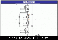
I guess, you didn't understand the operation principle of the NPC (neutral point clamped) inverter nor identified the said Boost Inverse Diode in the module block diagram. Otherwise you won't ask.

The diode is clearly showing up as a diode/zener combination, which clarifies the reason for unusual high "forward" voltage. It's basically a protection device, not intended to dissipate much power in regular operation. Anything else would be really surprizing for a module targetting to 99.x % conversion efficiency.

 
I agree, that the matter is complicated. The confusing point is that the "forward" voltage of the diode combination is mainly defined by a zener reverse voltage. It can be only understood by looking thoroughly at the module schematic. Unfortunately, the diode hasn't a designator, but the functional names "buck", "boost" are clear so far.
 
... because I have looked up several diode datasheets and non is comparable to that.

You are right, it is confusing.

I thought first since it is a 'preliminary' datasheet that Vf=9V might be a mistype error but it is mentioned twice; on the table and in figure 25, so this possibility is out of question. For instance, making Vf of a diode rather high is always possible by cascading several junctions. But the question that remains is; why 9V is chosen. The answer could be known, as FvM has already pointed it out, after analysing in depth a real complete circuit (Buck or Boost).

About its forward current of 2A and 20A, I think the latter is possible only if pulsed with a small duty cycle (Figure 26).

Kerim

Edited:
I wonder why they didn't call it a zener in the first place! :wink:
 
Last edited:
I guess, you didn't understand the operation principle of the NPC (neutral point clamped) inverter nor identified the said Boost Inverse Diode in the module block diagram. Otherwise you won't ask.

You are right. I'm not very familiar with this because I have only been looking up single discrete devices so far. Thank you for your help sir.

Cheers,
Law

---------- Post added at 01:23 ---------- Previous post was at 01:22 ----------

I would like to thank everyone for your time in helping me out with this. I really appreciate it.

Cheers,
Law
 

Hello Sir,
I really am new with this stuff so if it isn't too much to ask, can you please explain how this configuration works? Thanks in advance.

Regards,
Law

---------- Post added at 06:44 ---------- Previous post was at 06:42 ----------

I guess, you didn't understand the operation principle of the NPC (neutral point clamped) inverter nor identified the said Boost Inverse Diode in the module block diagram. Otherwise you won't ask.


Hello Sir,
I really am new with this stuff so if it isn't too much to ask, can you please explain how this configuration works? Thanks in advance.

Regards,
Law
 

can you please explain how this configuration works?
I must admit, that I don't know much more than the meanining of the term NPC. But I noticed that Vincotech has a number of application notes related to the topic.

Here's a basic explanation of the topology
 

Status
Not open for further replies.

Similar threads

Part and Inventory Search

Welcome to EDABoard.com

Sponsor

Back
Top