gres
Full Member level 4

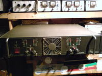
inspiration for that project was Nord kit with TDA 7250 as a driver for power level. Each bone consist two “STEREO” system with easy possibility to switch them into bridge.
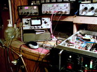
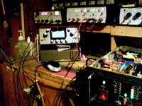
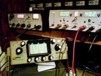
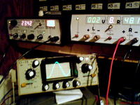
After I had put all elements together I plugged power, generator, oscilloscope, resistors battery as a dummy load and started testing. Firstly typical 1kHz and everything fine. Power ok, noise and other garbage low. Now time for 20Hz, firstly nice. I’m going higher and then… power transistors at one channel blows up. I put new one, but again – TRACH. Oscilloscope shows that amplifier is unstable. Solution for this problem was to change condensers from 150 into 220 pF.
Power: after analyst data from catalogue: http://www.datasheetcatalog.org/datasheet/SGSThomsonMicroelectronics/mXvrvuw.pdf i decided to use voltage close to maximum. as I didn’t have a lot space in casing I used 4 transfomers 200VA each, two per board and each with own bridge (25A/400V). one 15000uF/50V condenser per rile. Fuses 8A at power output to amplifier boards.
Connections:
Now you will understand the title. I had 4 independence endings and possibility of easy connection each pair into bridge – so I used that. Besides I need 2x300W/8 Ohm. Solution was simple; everything in application note and kit. Problem was how to prevent automatic switch columns from stereo mode to bridge. I used switcher, relay, ferredd swith.
Final effect: in stereo mode we have two double input slots and 3 output slots. Two for channels L, R 4 ohm columns and third for bridge 8 ohm.
More information at http://www.elektroda.pl/rtvforum/topic1561961.html
