Continue to Site

Welcome to EDAboard.com

Welcome to our site! EDAboard.com is an international Electronics Discussion Forum focused on EDA software, circuits, schematics, books, theory, papers, asic, pld, 8051, DSP, Network, RF, Analog Design, PCB, Service Manuals... and a whole lot more! To participate you need to register. Registration is free. Click here to register now.

5V device that will reset 3V device

Status
Not open for further replies.

TheMartian

Junior Member level 3
Joined
Jul 6, 2018
Messages
28
Helped
0
Reputation
0
Reaction score
0
Trophy points
1
Activity points
322
Hey
I have 3.3V PIC mcu and other MCU that is 5V.
3.3V PIC MCU has a standard button + 10k resistor to VDD RESET / MCLR circuit.
I want to add a circuit that will take the logic level from 5.0V device (5V or 0V) and let it toggle the 3.3V PIC reset.
So, basically, one device will reset the other device.

I have searched for long time and come up with two solutions:
1. JjskT.png
I think this would work if both logic levels were 0-5V, but in case that 5V is driving transistor with 3.3V on the other side I am afraid that the voltage difference will fry the transistor?
2.sol2.png
this is a second solution, I am not sure how it works, but I seen it on some board which is reset trough ftdi but I modified it.

IS any of my solutions valid or can you suggest me how to solve my problem?
 

Hi,

It's not clear to me how many reset sources exist. Nor do I know the polarity and the levels of each signal.
Maybe you could give an overview....

Klaus
 

It's not clear to me how many reset sources exist. Nor do I know the polarity and the levels of each signal.
Maybe you could give an overview....
Ah, sorry, I will try to explain the best I can.

There will be two reset sources:
- classic tactile button (like in Arduino)
- my circuit which I want to add
The "reset target" chip is 3.3V PIC and the RESET works great with button but I want to reset it from 0V-5V TTL level from other MCU as well. I will add my circuit as second reset method so I don't have to push the button every time.

So, I want to keep the button and 10k pullup at RESET/MCLR pin and just some kind of circuit which will act as second button but will be driven by 0V-5V TTL...

PS: I know I can do this with relay, but I want to do this electrically...
Is there anything that is still unclear?
 

Resets are usually active-low, so an open-drain / open-
collector output from the 5V device, and the pullup
resistor ought to do.

A NPN transistor with its base driven by the MCU
through (say) a 10K base resistor would probably
work too, but might be larger in the end than a
"tiny logic" single gate open-drain inverter / buffer.
 

Hi,

Still unclear.
Example:
- classic tactile button (like in Arduino)
* it can be NC or NO type contact.
* it can be connected to GND or it can be connected to VCC.
This results in 4 different circuits.

Why don't you take a piece of paper and a pencil to show your setup?

Klaus
 

Try to clarify the specification. I guess, both resets are active low, you want an unidirectional level translation from 5V to 3.3V reset?

In this case, a simple diode can do, if voltage drop is critical, may be a small signal schottky.

As for the presented circuits, circuit 1 is involving polarity inversion, circuit 2a is performing bidirectional conversion and you have copied it wrongly with flipped 3.3V and 5V nodes. As shown, the substrate diode pulls the 3.3V node to about 4.5V, might damage the 3.3V circuit.
 

Hi,

there are many threads about level conversion.

Noninverting 5V --> 3.3V
As a single part solution maybe 74AHC1G125 is suitable. Driven by 3.3V. 5V input tolerant.

Can be configured as:
* push-pull: input --> A; GND --> /OE
or as
* open collector: input --> /OE; GND --> A

Klaus
 
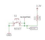
I meant the obvious RESET circuit for PIC/AVR, but I will reclarify as you wish:
sol2.png
RESET is microcontroller RESET/MCLR PIN, 3.3V is microcontroller VDD, and "my circuit here" is the place where I want to connect my transistor/mosfet circuit driven by 5V-0V that will cause the resset the same way pushing the button does.

FvM, are you saying that just a diode would suffice here?

I've been rather thinking about using 10k resistor at the base of transistor that would somehow pull the reset low as dick_freebird said, but what do you mean by "larger"?

- - - Updated - - -

Here is my current solution:
solution1.png
The 10k resistors at gate are placeholders, I think they will be around 200-1000Ohms, and I am not sure if pull down is necessary

The FTDI_DTR will be usually low, and MOSFET will be closed, but then I will change FTDI_DTR to 1, and it will open mofset and pull low the RESET pin....


it's based on Stack Overflow post:
What I'm doing in the same situation, is to use a BS170 (small-signal MOSFET N-channel) to pull the signal low when the Arduino pin goes high.

Arduino output -> Gate of MOSFET and Xbee Reset -> Drain of MOSFET. Source is tied to ground.

In general, I find MOSFETs easier to use for digital signals the BJT transistors like in the LadyAda tutorial.

You may also want to use a resistor (200 - 1000 Ohms) between the Arduino output pin and the MOSFET gate, to limit the current spike when switching. A MOSFET gate is like a small capacitor, only drawing current when changing state, but it can draw a lot of current for a very short while; there's a risk in very temporarily exceeding the 40 mA rating of the Arduino pins.

So, why do I thiink this is better than a solution that uses no intervening components? Two reasons:

1) With the direct pin tied, one small software bug might put the pin high and fry the Xbee. This is a very real risk. Don't ask me how I know :)

2) The Xbee RESET signal is not specified to any particular input capacitance, so you may end up sinking more current than acceptable when driving the output pin low on the Arduino. It's a small risk, but why take it?
Source: https://electronics.stackexchange.com/questions/36981/resetting-xbee-with-an-arduino
 

Hi,

* Now this is an inverting solution. (We asked about signal polarities or inverting, sadly you didn´t answer it. )
* and it´s a 3 part solution. (I provided a 1 part solution)

Only you can know if this is a good solution for you or not...

Klaus
 
* Now this is an inverting solution. (We asked about signal polarities or inverting, sadly you didn´t answer it. )
You mean that High state on driving pin will pull reset Low?

I think it's not the problem because I can control the driving pin from code. Also, I can decide myself whether I will pull it down or up by default (in case that driving pin mcu is not powered)?

As for your solution with 74AHC1G125 , are you saying that it will be okay without any external parts? It's interesting chip you recommended, thank you for it. I will read about it, compare prices and availablity and maybe use it in the end.
 

Hi,

You mean that High state on driving pin will pull reset Low?

I think it's not the problem because I can control the driving pin from code. Also, I can decide myself whether I will pull it down or up by default (in case that driving pin mcu is not powered)?
You know your requirements .. but you have to tell us to get suitable feedback. Else we have to guess (which wastes time and energy).

are you saying that it will be okay without any external parts?
--> yes, 1 part solution.

***
If you can live with inverting behaviour, then you may use a digital bjt with built in resistors. Like PDTC123JT => also 1 part solution.

Klaus
 

Status
Not open for further replies.

Similar threads

Part and Inventory Search

Welcome to EDABoard.com

Sponsor

Back
Top