saavedra29
Newbie level 5

Hello, it's nice to have found this forum! I've been messing for a month with electronics and try to create some kind of a small alarm, just to practice.
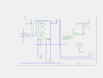
I have attached a png of the circuit i have created so far. A NOR gate takes input of at least one of two buttons, giving LOW output to the first 555n. This triggers and gives HIGH for some time ( depending on the potentiometers value ).
What i want is to take the HIGH output of this first 555n and control the VCC of a second. The second 555n gives a high frequency making a piezo speaker buzz. The problem is that i don't know how to make the first 555n's output work as a switch for the power supply of the second 555n. I have tried using a 2222 transistor but had no luck. As far as i know the transistor except from working as a switch it increases the current on the emitter, so it could ( maybe ) destroy the second 555n.
Well, i've been very confused at this point.:sad: Do you have any idea how can i fix it? I have attached the circuit in png ( designed with Geda ). Thanks.
( sorry if the design of the circuit is a bit confusing, it the first time i design an electronic circuit ).
Attachments
Last edited:


