Continue to Site

Welcome to EDAboard.com

Welcome to our site! EDAboard.com is an international Electronics Discussion Forum focused on EDA software, circuits, schematics, books, theory, papers, asic, pld, 8051, DSP, Network, RF, Analog Design, PCB, Service Manuals... and a whole lot more! To participate you need to register. Registration is free. Click here to register now.

555 and rectified ac Proteus

Status
Not open for further replies.

sirbuctin

Newbie
Newbie level 2
Joined
Oct 7, 2014
Messages
2
Helped
1
Reputation
2
Reaction score
1
Trophy points
3
Activity points
28
Hello,

I am trying to simulate a square wave with 555.
It works ok if i power the circuit with DC, but when i try to power from a rectified ac voltage source, 50hz, it does not work anymore.
I tried with Sine wave AC voltage source, also with Alternator, with or without transformer, with generic bridge rectifier or with 4 diodes, nothing works.
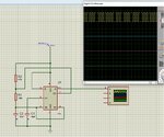
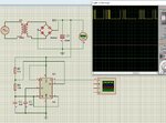
pic2.jpg
pic1.jpg
 

The 555 simulation model seems to behave different than the real chip.
 

Have you tried to connect an earth to the primary side of the transformer?
 

other than 50 Hz, what are the characteristics of the source?
what is the turns ration of the transformer?
what voltage do you expect on the output side?

how much current does the 555 circuit draw?

on the surface, it looks like the capacitor should hold up the
rectified AC, but the scope trace looks like it isn't holding up the DC

as Easy peasy says, look at pin 8 of the 555 carefully
please show the time scale of the 'scope

what is the reference for the 'scope traces?
 

Thanks for your answers,
I found that adding a diode after the filter capacitor to separate the circuit from it fix the problem. It is like the filter capacitor maybe influences the R2, R1, C1 series ?!.
I dont think a real circuit will have this problem, something may be wrong with proteus..
 
Status
Not open for further replies.

Similar threads

Part and Inventory Search

Welcome to EDABoard.com

Sponsor

Back
Top