Continue to Site

Welcome to EDAboard.com

Welcome to our site! EDAboard.com is an international Electronics Discussion Forum focused on EDA software, circuits, schematics, books, theory, papers, asic, pld, 8051, DSP, Network, RF, Analog Design, PCB, Service Manuals... and a whole lot more! To participate you need to register. Registration is free. Click here to register now.

How to count zeros in registers?

Status
Not open for further replies.

davyzhu

Advanced Member level 1
Joined
May 23, 2004
Messages
494
Helped
5
Reputation
10
Reaction score
2
Trophy points
1,298
Location
oriental
Visit site
Activity points
4,436
Hi all,

reg[7:0] register; (Verilog)
The register contains data like
[0 0 0 1 0 1 0 1]
And I want to know the number of the zeros before the first 1
(in this example is 3 zeros).

How to do this in a combinational logic?

All the logic have be done in Verilog :)

Best regards,
Davy
 

Cannot undersand what are you exactly trying to do!! You can put 7 LED if its a parallel output register.....if its serial you need to convert it into parallel first.
 

Just in case this is a homework problem, I'll give you only a hint. You can use a priority encoder.
 

    davyzhu

    Points: 2
    Helpful Answer Positive Rating
search of "normalization" and "VHDL". You will find the info you need.

Also this functionality is natively supported in some modern microprocessors. In their case, this operation is called: "FIND FIRST ONE".

the_penetrator©
 

    davyzhu

    Points: 2
    Helpful Answer Positive Rating
Hi,

It's a interview problem :)

I have solve it in priority encoder. But the circuit seems not balanced.

All the best,
Davy
 

haha is it an interview problem? i had it as a homework in my old logic class, except our assignment was find the number of zeros before the first one. i think your teacher just inverted my old homework.
 

shift the register contents and xor the previous output with the present one.
count the number of clock pulses elapsed till the output of xor is 1.
the number of clock pulses id ur answer.
 

The XOR technique sounds good to me. For visual and interactive circuits go here: **broken link removed**. It may help.
 

Hi,

You can find the answer at the first section in chapter 5 of Digital Design by Mano

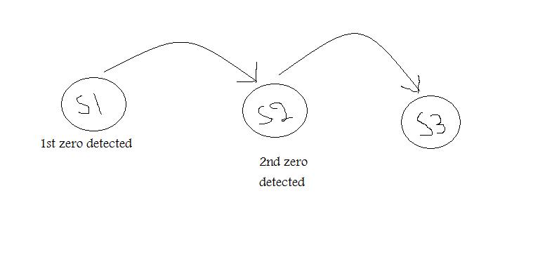
You won't reach your target unless you consider a sequential circuit design steps. the first thing is you should is to draw a state diagram.
85_1269542237.jpg
 

Status
Not open for further replies.

Similar threads

Part and Inventory Search

Welcome to EDABoard.com

Sponsor

Back
Top