theguardian2001
Newbie level 6

Hi, everyone! I have recently posted a thread about getting error in dc simulation for a folded cascode opamp. Please see it for a full explanation: https://www.edaboard.com/threads/er...gence-in-cadence-spectre.412563/#post-1781856
To keep things shorter: Cadence did not want to converge because it had not seen any resistance between drain and source of a couple of cascoded PMOSes. I tried several things to overcome the problem. The latest was simply inserting one more PMOS pair inbetween the original ones and the output terminal such that Spectre "skips" or "leaves shorted" the ones with zero rds - have not helped.
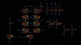
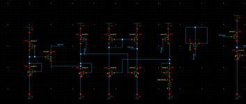
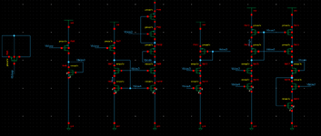
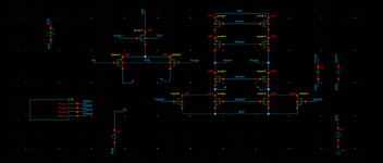
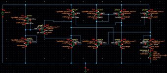
After a while I swithced the technology to free PDK45 thinking that the error was in the technology files. However, today I tried to test the new technology with the telescopic opamp. The results have almost freaked me out: for this technology by testing the op in the dc analysis all of the voltage headroom is now occupied by exactly these two PMOSes which have not consumed any voltage at all in the previous simulations (these are named in schematic as PM1 and PM2). So I am thinking that there is something wrong with the setup/simulator because the error appers for exactly the same devices. I am attaching schematic, testbench and log file. I would really appreciate any comment and advice regarding the issue.
P.S. Probably my explanation of the issue was not the best. However, in the context of the previous thread it makes much more sense.
