Continue to Site

Welcome to EDAboard.com

Welcome to our site! EDAboard.com is an international Electronics Discussion Forum focused on EDA software, circuits, schematics, books, theory, papers, asic, pld, 8051, DSP, Network, RF, Analog Design, PCB, Service Manuals... and a whole lot more! To participate you need to register. Registration is free. Click here to register now.

SIMCOM A7672S Power LED Blinking

avinash_g

Newbie level 6
Newbie level 6
Joined
Apr 9, 2008
Messages
11
Helped
1
Reputation
2
Reaction score
1
Trophy points
1,283
Activity points
1,359
Hello All,

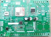
I have some strange hardware problem with some A7672S. I am using A7672 on a Custom made PCB, the hardware is all designed according to the recommendations provided by SIMCOM. PCB is assembled using automated equipment with proper SMD soldering. But some of the PCBs (50%) has some strange problem where the GSM Module (A7672S) is not able to power on. When A7672S successfully boots up, the POWER LED glows ON stable. As mentioned in the datasheet. But in some (say 50%) PCBAs, the (A7672S) is not able to power on, and in this case the power LED is blinking On/Off, this situation is not mentioned in any datasheet nor in any webpage (using Google Search). I mean what does it means by a blinking pulse on POWER LED PIN
If someone knows about it, please help.

TOP.jpg

IOT-GATEWAY-4G-PCBA.png

schematic.png
 

Attachments

  • TOP.jpg
    TOP.jpg
    739.6 KB · Views: 589
  • IoT-Cloud-Gateway-1.pdf
    106.5 KB · Views: 267
  • IoT-Cloud-Gateway-2.pdf
    97 KB · Views: 168
  • IoT-Cloud-Gateway-3.pdf
    87.6 KB · Views: 164
  • IoT-Cloud-Gateway-4.pdf
    57.1 KB · Views: 169
  • IoT-Cloud-Gateway-5.pdf
    58.2 KB · Views: 180
Since, some PCBs are creating problems, and some are working, I am sure there is no problem with your design. If the problem were with your design, all PCBs would have failed. I think it's a case of manufacturing error. Some PCBs may have broken traces or short circuits. It often happens. Test the problematic PCBs with a multimeter opening the circuit diagram in front of you.
 
I am sure there is no problem with your design.
I´m not that sure.
If one parameter is poorly designed .. so with a very low margin to get valid voltage levels ... the one board may work while the other not.

For example: If an input is left floating. Or a digital input is driven to a level between LOW and HIGH.

Klaus
 
The problem is that the what does the BLINKING pulses in POWER LED (status pin) is not mentioned in the datasheet. If any one knows what does this behavior indicates we can look into that direction and make corrections.
 
Hi,
The problem is that the what does the BLINKING pulses in POWER LED (status pin) is not mentioned in the datasheet. If any one knows what does this behavior indicates we can look into that direction and make corrections.
True.
If blinking is not mentioned .. then I see two reasosns:
* either it´s a (new) undocumented function
* or the blinking is not a true blinking feature at all.
It may be caused by a continous power_up and power_down repeat.
Or any other failure that causes the LED to switch ON and OFF "by accident"

Thus my idea is to investigate what happens and what is the root cause (of the blinking).
I´d check each module pin with a scope to see: (during failure = blinking)
* whether the supply voltage is stable
* RESET is stable
* each single voltage level is true HIGH or true LOW
* if there is unexpected oscillation
* whether connecting the scope changes the behaviour (like blinking frequency)

Klaus
 
Finally yesterday I have found the cause. The modules are all OK. But A7672S module's firmware was the trouble. It was preloaded with some strange version of the firmware that didn't behaved as mention in the datasheet. Like power LED's behavior was completely different and also weird. Same case with the NETWORK led too. The default baud rate was also not 115200 but 9600. But everything else worked fine. SIM was detected, network was connecting and HTTP was working good too.
 
I am using an A7672G module with ESP32 and my problem is, that the module boots up for 4-5 seconds and then goes off. I left the Power Key, which is not connected to anything because it's mentioned in the datasheet that the POWERKEY is pulled up with V_bat. Can You help me with this?
 

LaTeX Commands Quick-Menu:

Part and Inventory Search

Welcome to EDABoard.com

Sponsor

Back
Top