Continue to Site

Welcome to EDAboard.com

Welcome to our site! EDAboard.com is an international Electronics Discussion Forum focused on EDA software, circuits, schematics, books, theory, papers, asic, pld, 8051, DSP, Network, RF, Analog Design, PCB, Service Manuals... and a whole lot more! To participate you need to register. Registration is free. Click here to register now.

Need help in circuit simulation

engr_joni_ee

Advanced Member level 3
Joined
Nov 3, 2018
Messages
822
Helped
2
Reputation
4
Reaction score
7
Trophy points
18
Activity points
6,877
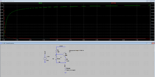
Hi, I need to change the value of PT1000 resistance from 900 Ohm to 1100 Ohm and probe the voltage across the PT1000
and also probe the current through it. I am not sure how to setup run man settings. Please guide me with the settings.

Thanks in advance.

Untitled 636.png
 
Hi,

Let´s do some simple "ohm´s law math".

The TL431 regulates for 2.495V ... across your 100 Ohms.
So let´s calculate the "constant current": R = V/I ==> I = V/R = 2.495V/100 Ohms = 24.95mA

Now you connect your PT1000 to this 24.95mA. You want it´s range to be 900 Ohms to 1100 Ohms.
So let´s calculate the voltage across the PT1000:
R = V / I ==> V = R * I = 900 Ohms * 24.95mA = 22.455V

Basic question:
Are you aware that it´s impossible to get 22.455V across the PT1000 ... while your supply voltage is given with 3.3V only.

--> in such linear circuits there will be no higher voltage anywhere than in the power supply. It´s always less.

The circuit can´t opreate properly!


Klaus
 
Review LTspice help to understand why this can't work. DC sweep is for independent voltage and current sources only. Iout is a node name in your schematic, no legal sweep target. You can use a a simple Pt1000 model with temp parameter sweep.

1712565738502.png


I understand that the circuit refers to previous thread https://www.edaboard.com/threads/solving-iout-tl431.410567/
Just want to mention that your 100 ohm resistance values are completely out of range.
 
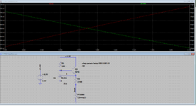
I have changed the value of Rs to 2700 Ohm. Assuming that 2.495/2700 = 0.92 mA current as through Rs. Assuming Ika is small, so the current through the PT1000 should be the 0.92 mA + Ika but the current is changing a lot. How can the voltage is proportional to the resistance. Also I am not getting the PT1000 resistance on the x-axis between 900 Ohm to 1100 ohm.
 

Attachments

  • Untitled 639.png
    Untitled 639.png
    37.4 KB · Views: 112
Hi,

Did I mention I don´t like this circuit? Maybe you now get some clue "why".

***
To the circuit.
You correctly calculated the "regulated" current to be 0.92mA

But the simulation is far away from "accurate" 0.92mA.
Again some simple Ohm´s law (which I do here for the last time.. because imho ofter 6 years mebership on edaboard it´s high time that you can do this on your own)

Let´s say Pt1000 to be 1kOhm.
Now let´s do some math for the path: 3.3V -> R1 -> BE of Q1 --> RS --> PT1000. but back from bottom to top.
* Voltage across PT1000 = 1k x 0.92mA = 0.92V
* Voltage across RS: 2.495V
* Voltage across BE: 0.55V
* Voltage across R1= the rest to add up to 3.3V: 3.3V - (0.92V + 2.495V + 0.55V ) = 3.3V - (3.965V) .... ALARM! the value in the brackets already is HIGHER than 3.3V
and the voltage across R1 can´t be negative (it is no power source, no battery)

--> thus, simple answer: it´s impossible to work!

If you use the TL431, then the 2.495V (and tolerance) is unavoidable.
now if you use a 3.3V supply, then remaining voltage for the rest is 3.3V - 2.495V = 0.805V
Now V_BE of a standard Bjt may be in the range of 0.55V mabe 0.6V.
So subtract the 0.6V from the 0.8V and you get tiny 0.2V for (R1 + PT1000)

*****

The electrical problem is a simple as stapling boxes of different heights in a room with a dedicated height.
If a room is 3.3 (no matter whether you want to use feet, meters, yards...) in height and you have 4 boxes to staple to exactly match the height of the room.
Name the boxes: R1, Q1, RS, PT1000,
Name the height of the boxes: V_R1, V_BE_Q1, V_RS (which is VRef of TL431), V_PT1000.

If one box is 2.945 in height and the other box is 0.805 in height you can´t staple them in a room of 3.3 height. It´s impossible.
.. and for sure you can´t staple 2 additional boxes. Boxes can´t be of negative height.

So either you need to adjust the height of the boxes, or the height of the room, or both.

*****

For sure you may play around with constant current sources .. if you have high enough supply voltage.
If you use a microcontroller and want a simple solution: use VRef of the ADC and a 1k resistor. Then do the simple math in software. It´s easy and it´s precise, cheap, small...

We don´t know your requirements. And there may be situations where you can´t get around a true constant current source (like using a DVM across the PT1000).

Maybe this is a school project .. and you need to use a constant current source .. we don´t know.
But maybe it´s an application and your requirement is: read temperature (from time to time) in the range of MIN .. to MAX with max error of MAX_ERR.
Then tell us these three values marked in capital letters.

Klaus
 
Last edited:
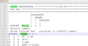
I am sorry. There was a mistake on pin numbering because I just modify the autogenerated symbol in LT Spice. The pin numbering is fixed now. The current changes between 710 uA to 668 uA through PT1000.
 

Attachments

  • Untitled 641.png
    Untitled 641.png
    46.2 KB · Views: 100
  • Untitled 642.png
    Untitled 642.png
    24.9 KB · Views: 95
KlausST has explained why the circuit can't work with 3.3V supply (TL431 doesn't regulate). Need to reconsider component or supply voltage choice.

My favorite Pt1000 measurement circuit uses essentially three components:
- high precision reference resistor
- Pt1000
- 16-Bit delta-sigma ADC
Reference resistor and ADC are powered by 2.5-3.3V analog supply. Voltage divider transfer function and Pt1000 curve are corrected in software.
 
Sorry I did not read reply #5. Yes it's true it will not work with 3.3 V. I change the supply voltage to 5 V.

I reduce the value of R1 to 900 Ohm.

Starting from the current through Rs = 2.495/2700 = 0.92 mA

Adding voltage from top to bottom.

V_R1 (900 * I) + V_BE (0.6) + V_REF (2.495) + V_PT (1100*I)

900 * I + 0.6 + 2.495 + 1100*I = 4.94 V.

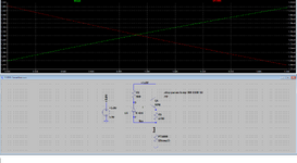
Still current is changing even though there is no temperature drift on the chip, see attachment. According to data sheet "Sink-current capability: 1 mA to 100 mA".

I guess I am missing cathode current Ika. Or this chip can not be used as 1 mA current source at all ?

Regarding the temperature range and accuracy. We would like to measure the temperature between 0 degC to 120 degC. The accuracy/offset can be 2 degC which can also be adjusted in software.

Regarding, the voltage divider approach with amplifier and ADC, I will simulate it latter.
 

Attachments

  • Untitled 643.png
    Untitled 643.png
    51.8 KB · Views: 107
This post was created to solve a problem in circuit simulation because it was not able to apply the variable resistance. The problem was solved by step command in LT Spice. Then it turned into using TL431 as current source for RTD. We found that it did not work. Let's close this post. Regarding reading RTD I found another device that converts RTD to analog signal. In case of any problem I will put up a new post.
 
Hi, I need to change the value of PT1000 resistance from 900 Ohm to 1100 Ohm and probe the voltage across the PT1000
and also probe the current through it. I am not sure how to setup run man settings. Please guide me with the settings.

Thanks in advance.

View attachment 189886
I don't recall your specs for Temp. range and accuracy with supply tolerance.
 

LaTeX Commands Quick-Menu:

Similar threads

Part and Inventory Search

Welcome to EDABoard.com

Sponsor

Back
Top