Continue to Site

Welcome to EDAboard.com

Welcome to our site! EDAboard.com is an international Electronics Discussion Forum focused on EDA software, circuits, schematics, books, theory, papers, asic, pld, 8051, DSP, Network, RF, Analog Design, PCB, Service Manuals... and a whole lot more! To participate you need to register. Registration is free. Click here to register now.

3ph DC motor control board damaged with arduino output signal

eagle1109

Full Member level 6
Full Member level 6
Joined
Nov 20, 2014
Messages
393
Helped
4
Reputation
10
Reaction score
7
Trophy points
1,298
Location
Saudi Arabia
Activity points
5,956
Hello,

I'm working on this project which is to control a 3ph dc motor using a 3ph dc motor control board:

Note: this picture has been taken before finishing the wiring.

1707582032059.png


1707581738191.png


This is the control board layout:

1707581972838.png


This is how I connected it with the arduino board:

1707590526342.png


But the problem, first time I tried to pull this line using the arduino, I heard like glitching sound and everything shutdown, the 24V power supply, the controller and the arduino board.

I knew there must be a short pulling this line to 0V, but why?
--- Updated ---

I forgot add this:

I took pictures for the board, after checking out the pictures, I found that this is a cracked diode.

20240206_164615.jpg
 
Last edited:
Without the arduino, the control board work with no problem at all.

Just connect the control terminals with a switch or push button with ground for active low pins and only one require active high signal.
 
Yes, the exact wiring in the diagram I posted.

I think pulling that pin to ground sourced a lot current from or to the arduino.

The problem is that there's no voltage involved. The arduino pin is pulled to ground and the controller pin is also pulled to ground.

And the controller doesn't take pulling its pin to ground as a short. Because even in the board layout it says the pin should be connected to ground.
 
The arduino output pwm signals?
Why you not connect the hall sensor?
The jumper in board is open?
 
Last edited:
Hello,

I'm working on this project which is to control a 3ph dc motor using a 3ph dc motor control board:

Note: this picture has been taken before finishing the wiring.

View attachment 188538

View attachment 188536

This is the control board layout:

View attachment 188537

This is how I connected it with the arduino board:

View attachment 188539

But the problem, first time I tried to pull this line using the arduino, I heard like glitching sound and everything shutdown, the 24V power supply, the controller and the arduino board.

I knew there must be a short pulling this line to 0V, but why?
--- Updated ---

I forgot add this:

I took pictures for the board, after checking out the pictures, I found that this is a cracked diode.

View attachment 188544
The doide open now?
 
No, it's still working even with the crack.

Maybe I have to take the diode out. It could sharing resistance with other components.
 
No, it's still working even with the crack.

Maybe I have to take the diode out. It could sharing resistance with other components.
Yes , replace better
Also , I see two gnd at the arduino board, are they the same or different?
 
Also , I see two gnd at the arduino board, are they the same or different?
One for the motor control board and one for the LCD.
--- Updated ---

What did you do bro?

Maybe the problem from the pushbutton connection.

Maybe the board requires the connection to be only from the same board's GND or VCC. It may not accept connections from external sources like the Arduino. I don't know why.
 
Last edited:
I think gnd must be same , for control board and for output signals from arduino
I did that, it's obvious in the picture.

Maybe the connection of the controller board requires an open collector circuit if I want to control the board from another board like the arduino or any other 5V logic controller.
 
Your board may have been wrecked. If you fix it, then along with those of others, there are a few observations you'd need to take of.

First, do you realize that these two boards that you posted on post #1 are different?
Screenshot_20240221-034646_1.jpg

--- Updated ---

You did not connect the hall sensors. Are you not using them?
--- Updated ---

Screenshot_20240221-040653_1.jpg
Also, you need to study these switches and their active states to determine how to interface your Arduino to those terminals. Which of them is forward, reverse, stop? Notice that the red line is wired to +5V (which means high input when tge switch is closed) whereas the two black ones are wired to GND (which means low input when the switch is closed).
--- Updated ---

Screenshot_20240221-043123_1.jpg
Also, make these adjustment.
 
Last edited:
I suspect your 3ph motor expects a low d.f. PWM to reduce the current and inertial BEMF power (stored energy) without PWM will burn out the diode.

pls. show links to controller and motor. I doubt your board is rated for a large DC Stepper motor. You must use a current limited 3ph Stepper driver with heatsinks and an adjustable current limit using 3 full bridge FET drivers with a PWM controlled current limiter.

You could try replacing the diodes with power resistors such that Imax *R does not exceed 24V or driver voltage limits.

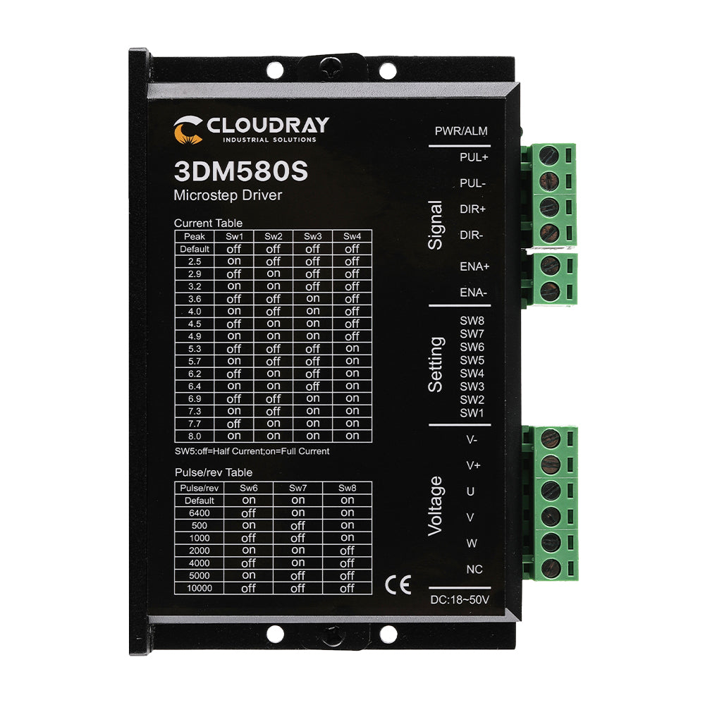
I have one of these. https://www.amazon.ca/3-Phase-1-0-8-0A-18-50VDC-Smartrayc-Discounts)/dp/B07DQPCRRN?th=1

1708492750992.png

Try it at 6V and test it out for thermal rise then raise the voltage with minimum current adjustment after replacing the diodes with power brake resistors and power Sch. diodes in series.
It's already broken, nothing to lose.
 

Attachments

  • 1708492623856.png
    1708492623856.png
    278.1 KB · Views: 123
Last edited:
Your board may have been wrecked. If you fix it, then along with those of others, there are a few observations you'd need to take of.
The board still works, it's just the stop input is a pull-up and used to have 5V.

But after the problem happened with the interfacing of the arduino board as I was trying to control this input with the arduino and caused that problem.

Then input doesn't have that 5V anymore and of course a component connected to this input is damaged and I'm suspecting the diode I posted in #16. But also the input still work as it has now like 0.5V and if I pull it to 0V, it works and stop the motor.

1708535042273.png


First, do you realize that these two boards that you posted on post #1 are different?
OK, now I noticed it.

Yes, but the important is that my setup is in the picture in #1. This one I must have chose it by mistake.

You did not connect the hall sensors. Are you not using them?
I'm connecting them, it's obvious in #1. That's my real setup.

Also, you need to study these switches and their active states to determine how to interface your Arduino to those terminals.
That's the problem is that there is no source of datasheet of application file for this board.

Which of them is forward, reverse, stop?
Yes, this one is easy according to the simple wiring layout I posted here. It's the same.


Notice that the red line is wired to +5V (which means high input when tge switch is closed) whereas the two black ones are wired to GND (which means low input when the switch is closed).

Yes, the black ones are a pull-up inputs and must be connected to GND to activate it. The red one is a pull-down and must be connected to 5V to be activated.
--- Updated ---

Thanks a lot man I thought it's a Zener diode.

OK, I hope replacing this diode fixes the problem.
 

LaTeX Commands Quick-Menu:

Part and Inventory Search

Welcome to EDABoard.com

Sponsor

Back
Top