Continue to Site

Welcome to EDAboard.com

Welcome to our site! EDAboard.com is an international Electronics Discussion Forum focused on EDA software, circuits, schematics, books, theory, papers, asic, pld, 8051, DSP, Network, RF, Analog Design, PCB, Service Manuals... and a whole lot more! To participate you need to register. Registration is free. Click here to register now.

Modeling negative feedback circuit with opamp to single or two transistor circuit

Status
Not open for further replies.

azadfalah

Full Member level 2
Full Member level 2
Joined
Aug 13, 2016
Messages
145
Helped
1
Reputation
2
Reaction score
2
Trophy points
1,298
Activity points
2,425
Hello friends

Can the part mentioned in the circuit below be modeled with the help of one or two BJTs?
The culprit of the question is, can the mentioned negative feedback operation be implemented in a simpler way but with the same stability?

ornek-uc3843-smps-charger.jpg


We assume that the reference voltage is 0.7


I found a close circuit but not sure if it is as stable
2095005500_1496238737.png


Thank
 

Hi,

Stable .. in the meaning of:
* not oscillating: maybe
* low drift: no

Klaus
 

Hi,

you don´t know what it is for ... and why, do you?

It´s an integrating capacitor put in the feedback of an OPAMP to generate an integrator circuit.
An integrator is used to get a zero error regulation loop.
You can´t do the same with a 1 or 2 BJT circuit.

****

For most circuits there is a reason why it is designed the way it is.
For sure you are free to modify a circuit .. but then at least you should
* know why you want to modify it
* understand how the one circuit works ..
* know what consequences your modification causes.

Klaus
 
Classic Miller Integrator, just google "bjt miller integrator schematic" for starters.


Regards, Dana.
 
Can the part mentioned in the circuit below be modeled with the help of one or two BJTs?
What is the purpose of doing that?
The BJT circuit will require more parts, likely cost just as much, and the supply output will have poorer regulation and accuracy.
 
Short answer: No. but it depends on your error and noise expectations.

Long answer: The 1/2 Op Amp in question performs the useful task of partial integration of current feedback to limit the average peak current with a trimmer for variable breakpoint to unity inverting gain. Voltage and current negative feedback will improve the resulting response time for error correcting to load changes.

Q1 in the 14.2V battery charger which uses a common base in reverse for near unity gain but no integration.

As others have correctly indicated, why degrade performance to save a few pennies.

In the original circuit, the partial integrator uses the high DC open-loop gain with the sensed current and a reference Zener voltage. The 4k7 pot + 220R under the yellow circle control the low frequency (integration) gain for correcting current limiting on pulses. Using current feedback to cut the regulator and anticipate over-charging is faster than waiting for the voltage to rise above the reference. This improves the stability of the battery charger to varying loads and reduces overshoot.

The opto-couplers use two LED's to indicate over-voltage feedback pulses and over-current pulse so the intensity of these indicate the amount of dynamic error from each source of feedback.

Judging by the faded colour of the paper schematic, looks like it came out of an old book with crystal radios.
1698778415824.png

--- Updated ---

old Hungarian schematics perhaps. https://circuit-diagramz.com/battery-charger-flyback-smps-modifiyesi-schematic-circuit-diagram/
 
Last edited:
If R6 is say 1k on T1 in the new ckt, then you can add a cap from base to emitter, say 100nF to filter the signal from the curr sense resistor R5, the Vbe will be about 0.55V - depending on xtor used, so for 500mA say, R5 = 0.55 / 0.5 ~ 1 ohm say, the Vbe varies with temp, approx 0.7V at -10 deg C, and closer to 0.45 @ 80 deg C

so the curr limit will vary with temp.
 
Your schematic missing component values is less reliable. Consider one with more details and a bigger cap across Vce of T1 and the causes of thermal variation. View attachment 185918

Thank you, it is an interesting circuit

If we want to make changes so that the battery does not discharge during a power cut, what do you suggest?

Thank
 

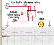
Low battery shut-off can be done by a relay. Relays usually cut out when coil voltage drops to say 50-60 percent of the rated voltage. By installing an inline resistor you can release the relay at some desired voltage.

Relays tend to have built-in hysteresis, meaning the coil-pull-in voltage is greater than the coil-release voltage. It avoids relay 'chatter' effect. Notice this simulation has the relay releasing just above 10V, then energizing again when battery is touching 14V (that is, recharged).

Transistors can be incorporated if desired in order to make adjustment more versatile and less finicky.
 

Attachments

  • relay coil series resistor sense low bat'y 12V.png
    relay coil series resistor sense low bat'y 12V.png
    50.8 KB · Views: 138
If we want to make changes so that the battery does not discharge during a power cut, what do you suggest?
You could also use a series P-MOSFET in the output, switched by an an opto-coupler controlled by the input power, if you want to avoid a mechanical relay.
 
Status
Not open for further replies.

Similar threads

Part and Inventory Search

Welcome to EDABoard.com

Sponsor

Back
Top