Continue to Site

Welcome to EDAboard.com

Welcome to our site! EDAboard.com is an international Electronics Discussion Forum focused on EDA software, circuits, schematics, books, theory, papers, asic, pld, 8051, DSP, Network, RF, Analog Design, PCB, Service Manuals... and a whole lot more! To participate you need to register. Registration is free. Click here to register now.

Whats wrong with 17W Offline Buck converter?

Status
Not open for further replies.

cupoftea

Advanced Member level 6
Joined
Jun 13, 2021
Messages
3,059
Helped
62
Reputation
124
Reaction score
139
Trophy points
63
Activity points
15,963
Hi,
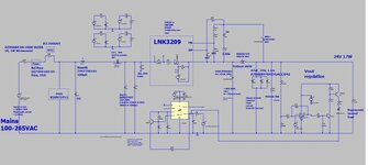
Why is this attached Buck deemed to be so bad? (100-265VAC input)
The LNK3209 is run within its current and voltage rating.
The inductor is within ratings.
The SiC diode within ratings.
The circuit will have loads of blown air over it all the time.
So why is it deemed a no-go'er?

LTspice and jpeg attached

LNK3209
--- Updated ---

Sorry forgot to say vout = 24V, 17W
 

Attachments

  • LNK3209 Buck 17W 24V.jpg
    LNK3209 Buck 17W 24V.jpg
    128.1 KB · Views: 195
  • Buck 100vac to 17w_LNK3209 _BEST5.zip
    3.9 KB · Views: 143
Last edited:

There are two things worth considering. Firstly, using only one input high-voltage rectifier diode is easily damaged, and at least two need to be connected in series (the answer can be found in the diode specification book). In addition, when LNK3209 is damaged, the load will withstand high voltage and be damaged. It is recommended to increase the power of the 3209 power supply circuit as an output while also supplying power to the 3209.
 

--> ask those people who "deem it to be a no goer".
Thanks, yes, that would be the makers of the chip (power integrations)...they wont give us any technical reason, despite repeatedly asking them.
They recomended we do a buck boost design instead, giving a -24V, 17W output.....and i guess they intend us to deal with that to get our wanted output.........but they didnt say why a buckboost......i have a funny feeling that in their labs, they have tried it in Buck topology, and it didnt work, but maybe they dont know why(?)......not sure really. They also recomend a flyback instead, but again, dont say why not the Buck.

There are two things worth considering. Firstly,
using only one input high-voltage rectifier diode is easily damaged, and at least
two need to be connected in series (the answer can be found in the diode specification book).
In addition, when LNK3209 is damaged, the load will withstand high voltage and be damaged.
It is recommended to increase the power of the 3209 power supply circuit as an output while
also supplying power to the 3209.
Thanks, but one 1kV diode will be fine IMHO.
If LNK3209 is damaged, then so be it....the fuse will blow.......theres no reason why it should become damaged in large occurrence.
We supply power to the LNK3209 as per the datasheet and app note AN-70.....it bascially gets a bootstrapped supply from the 24v output.....(we havent built it yet but thats what we intend)
 

    Calm down

    Points: 2
    Helpful Answer Positive Rating
Thanks, yes, that would be the makers of the chip
What?

The makers of the chip say the chip has some problems ... no additional information?
And you still want to use it?

Neither the one nor the other makes sense.

Klaus
 
If you see the schem we have...(top post).....it does not stress the chip in any way.....they say it is good for buck to 12v 1a output , but not for 24v 0.7a output .......doesnt make sense....Ayk, .the chip, in any case, doesnt know what the output voltage is anyway...it just knows the divider voltage. Why not 24V?
There is nothing in the LNK3209 datasheet that suggets it cant do 24v 0.7a from 100-265vac input.

No technical reason has been told to use as to why lnk3209 cant do 24v 0.7a output....just instead...telling us not to do it...without saying why........if you want to buy an Audi A6.....and the Audi dealer says to you...by the way...you cant drive it in Berlin....you are going to say.....hey....why not?.....and they tell you...."it just wont work in Berlin"....you are going to want to know why not....there is no reason a Audi A6 wont work when in Berlin.

We have to look into it with LNK3029...since its much cheaper than using a non isolated flyback.
 

What am I missing? Post #1 doesn't refer to any critical analysis of the shown design. Is it a riddle?
 

Thanks, yes, that would be the makers of the chip (power integrations)...they wont give us any technical reason, despite repeatedly asking them.
They recomended we do a buck boost design instead, giving a -24V, 17W output.....and i guess they intend us to deal with that to get our wanted output.........but they didnt say why a buckboost......i have a funny feeling that in their labs, they have tried it in Buck topology, and it didnt work, but maybe they dont know why(?)......not sure really. They also recomend a flyback instead, but again, dont say why not the Buck.


Thanks, but one 1kV diode will be fine IMHO.
If LNK3209 is damaged, then so be it....the fuse will blow.......theres no reason why it should become damaged in large occurrence.
We supply power to the LNK3209 as per the datasheet and app note AN-70.....it bascially gets a bootstrapped supply from the 24v output.....(we havent built it yet but thats what we intend)
If the effective value of the input AC voltage is Urms, then its peak value is 1.414 * Urms;

Therefore, the output voltage of a unidirectional half wave rectification circuit with capacitive filtering is Uo=1.414 * Urms;

In this way, when the input voltage is the maximum value of negative half cycle, which is -1.414 * Urms,

The voltage at both ends of this diode is equal to 1.414 * Urms - (-1.414 * Urms)=2.828 * Urms.

For example, if the input power supply is 220V rms AC mains, the maximum voltage at both ends of the diode for half wave rectification is:

2.828 * 220=622.16V. 240 * 1.1 * 2.828=746.59V 1N4007 (RMS)=700V
Thanks, yes thats right, but that just means we need a rectifier with high enough V rating, and we have that.
--- Updated ---

What am I missing? Post #1 doesn't refer to any critical analysis of the shown design. Is it a riddle?
Thanks, ill submit the analysis if you wish.....but i believe , by inspection, you can see that such a buck converter is well within the bounds of possibility for this chip, according to its datasheet....specially since we have loads of blown air over the cctry all the time.
 

Hi,

in the end I don´t care about "unfounded claims" of an application engineer.
The datasheet is what I rely to.

And datasheet circuits are usually maked as "recommendation". There is no need to use the chip exactly "as recommended". You may vary the circuit - as long as you keep within the datasheet specifications.
If the chip fails, then they faild to specify their chip correctly.

On the other hand, if I encounter a chip to fail while operating within specifications, ... I see it as my job to inform the manufacturer about this. Then - if they do their job properly - they have to check the situation and maybe have to update the datsheet.
It´s not an easy task to write a datasheet and they can´t test every imaginable circuit or situation. It´s part of a "development" and development means "a process with feedback".

Klaus
 
The question is  who said it's a bad circuit and  why they think so?
Thanks, Power Integrations (various of their apps engineers) advise us not to do Buck for 24v 17w.....they do not say why. They instead just tell us to do a buckboost for -24v, or a flyback....but not Buck.
 

This suggests problems with LNK3209 buck when vout is high
 

Status
Not open for further replies.

Similar threads

Part and Inventory Search

Welcome to EDABoard.com

Sponsor

Back
Top