Continue to Site

Welcome to EDAboard.com

Welcome to our site! EDAboard.com is an international Electronics Discussion Forum focused on EDA software, circuits, schematics, books, theory, papers, asic, pld, 8051, DSP, Network, RF, Analog Design, PCB, Service Manuals... and a whole lot more! To participate you need to register. Registration is free. Click here to register now.

FET's blowing up occasionally in solenoid valve mains control circuit

Status
Not open for further replies.

userx2

Full Member level 3
Full Member level 3
Joined
Sep 19, 2008
Messages
177
Helped
2
Reputation
4
Reaction score
3
Trophy points
1,298
Activity points
3,092
Hello,
I must admit, I have always had problems with Fet's not lasting in many applications I have used them as well as seen used by others.
This ranges from welding machines, light dimmers, motor controllers etc.
I never found the real reasons why this happens.
One other designer told me once that he moved away changed his designs to use IGBTs instead since they do not seem to have this issue.

Now I have a circuit that a former colleague of mine designed into one of our products. This one controls a 240V mains operated solenoid valve.
Now, about a year or so down the line, failures have started to emerge where the Fet's are burned out and there is again no easy explanation.
I am now considering changing the circuit to use a triac instead. They do last but have more power dissipation and heat generation

Perhaps someone here has better experience and can share their thoughts what may be happening here?
The solenoid is 230V 6W

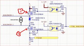
The circuit looks as attached. There are 2 Fets and 2 opto isolators to drive the gate voltage.
Either one or both Fets go faulty and will be cracked open or just black bits remaining.
I personally cannot find anything underrated or wrong with the circuit. The mains has MOVs on it as well at the input of the PCB.
Q2 and or Q6 seem to blow up. So far, it is 5 out of 200 delivered units and it happens after a month or longer. Hard to say what customers do with the unit.
The solenoid itself is usually found open circuit as well (yes open, not shorted).

Solenoid circuit 1.JPG
 
Last edited by a moderator:

what are L and N?
i assume solenoid 1 and solenoid 2 go to the solenoid - it is better to show said solenoid.

how much headroom did you allow on the voltage and current the FETs see?
230V 6W means about 37 A ??
i think this 1A rated FET is way too small
i'm surprised it didn't blow up the first time you activated the solenoid.

"240V mains operated solenoid valve" mains meaning AC power?
is it rectified? filtered? please show that part also
and anything else that's missing, especially anything involved in the path of the current through the solenoid
 

230V 6W equals ~26mA if my math is right.
I'm guessing this is a voltage spike problem but I'm curious to know why two MOSFETS are used as an AC switch when an opto triac would do it cheaper.

Brian.
 

Thanks for the replies.
L and N are mains Live and Neutral.
Yes, solenoid 1 and 2 are the solenoid connections.
The solenoid does not appear on the schematic as it is a separate unit and gets connected via a connector.

I did not observe any switching transients withe the scope. Solenoid transients are also clamped by the D7 TVS that is across it.
The solenoid is rated for 115mA Inrush and 65mA holding current @ 0.69 power factor

The Fets are rated for 600V
Id = 0.4A @25dC
Id = 0.25A @ 100dC
I would not expect that PCB to be hotter than 50dC.
There seems to be plenty of headroom.
--- Updated ---

230V 6W equals ~26mA if my math is right.
I'm guessing this is a voltage spike problem but I'm curious to know why two MOSFETS are used as an AC switch when an opto triac would do it cheaper.

Brian.
Well, 2 are required to work for both mains half cycles. I believe they were used in this case because they have advantages over Triacs in that they dissipate less power and are smaller. But I was not present when this was decided and the designer is now not present :)
 
Last edited:

Scope setup, were you in normal triggering and set for - level trip point ? High sample rate ?[

1663029755320.png


Regards, Dana.
 

It is not as simple here since both sides of the solenoid get switched.
For any Fet to see a large transient and blow up, it will require a high transient across that Fet.
I am not sure how that could happen here. since the TVS across the solenoid will not allow this.

I am thinking that the worst case would be the max transient (= clamping voltage of the TVS) + the Max AC half cycle voltage.
I will check that.


These also do not operate at a high duty cycle. They switch on for maybe 1 minute and then off many minutes or even hours.
--- Updated ---

Here is the schematic again, showing the solenoid in place. (Someone was not sure).
There is only 1 solenoid in this circuit.
 

Attachments

  • Solenoid circuit 1.JPG
    Solenoid circuit 1.JPG
    287.4 KB · Views: 349
Last edited:

If one of the MOSFETs shorts, then there is a large half-wave current through the solenoid and the other MOSFET substrate diode.
The current now looks like pulsed DC when causes a large current through the AC solenoid, which then causes the coil to overheat and open.

Hard to tell what might be causing the failures, but a factor could be high turn-on currents generated if the MOSFETs are turned on during zero-crossing of the AC voltage, depending upon the magnetic saturation and hysteresis characteristics of the solenoid (see this).
Intuitively you would think turning them on at the zero-crossing would be best but the opposite is true for highly inductive loads.
So it might be prudent to add a circuit that turns on the MOSFETs only near the peak of the AC voltage.

To illustrate this, below is the simulation of an inductor with the AC starting at the zero crossing (yellow trace) and 90° (red trace).
Notice that the zero crossing, 1st cycle, peak inductor current (green trace) is twice the 90° (blue trace) current, which could cause magnetic saturation and very high current in a real solenoid for the zero crossing case.

1663033185834.png
 
  • Like
Reactions: userx2

    userx2

    Points: 2
    Helpful Answer Positive Rating
The simple explanation for applying the voltage at the 90° point is that, for steady-state operation of an inductor with AC applied, there is a 90° phase-shift between voltage and current, so the current is at zero when the voltage is at its peak.
Thus if you activate the inductor with the voltage at its peak, you are starting at the steady-state conditions, so there is no transient start-up inductor current.
 

    userx2

    Points: 2
    Helpful Answer Positive Rating
Understood. But what is very interesting is that the current is actually higher than normal operating current in this case. Is it correct to say that the current will normalize after a few cycles?
I need to also measure the inductance of the solenoid and I am guessing all this varies, depending on the load/ liquid pressure.

So 1 possible failure mode could be:
1) Turn on at zero cross and high current blows 1 FET open circuit or short circuit.
2a) If short circuit, then the solenoid will remain on but on a half wave voltage, possibly overheating it and causing it to fail. This may however cause a system fault as the tank would eventually overflow
or
2b) If open circuit, the remaining FET will then supply the half wave only when the solenoid is on and possibly then burn out the solenoid.

I will definitely investigate this further.


There was another assumption that the solenoid goes short circuit first, burning out the FET(s) and then goes open circuit after some time. That one is somehow not as plausible.

Regards
X
 

Hi,

if a MOSFET dies there are only a few reasons:
* overvoltage (even extremely short time)
* overcurrent (even short time: see SOA)
* overtemperature of die (it depends on ambient temperature and dissipated power)

In your case the most probable reason is overvoltage. Here even spikes in nanoseconds duration may lead to long term failure.
Usually it´s overvoltage across D-S. If you want to protect a MOSFET against D-S overvoltage: The most straight forward method is to use
* a fast enough protection device
* directly connected to DS
* with as short as possible traces

In your case the TVS is across the solenoid ... thus the TVS protects (in first place) the solenoid against overvoltage.
It does not protect against overvoltage caused by stray inductance, overvoltage spikes from mains, not even common mode voltage (like ESD) when the solenoid is OFF. In case of OFF the node is floating at all.

The problem with "fast transients" is that every wire/trace acts as an inductor. And - very important: it does not matter (much) how wide/thick the trace/wire is.
While you can compensate the resistance of lengthy wires with bigger cross section this is impossible for the inductance.
--> You can not compensate the the inductance of a trace/wire by using thicker or wider traces.

This is why the wiring/PCB_layout is important.
You may use the most advanced.]high spped, expensive protection devices .... and they may be completele useless because of a bad PCB layout.

Klaus
 
  • Like
Reactions: userx2

    userx2

    Points: 2
    Helpful Answer Positive Rating
what is very interesting is that the current is actually higher than normal operating current in this case.
Yes, and it can get very high if the solenoid magnetics saturate due to the transient high current, since then the current is only limited by the solenoid coil resistance.

So how feasible would it be to add circuitry to turn on the solenoid at (or near) the peak AC voltage?
For example, the peak point could be detected by an op amp configurated as a differentiator.
Is it correct to say that the current will normalize after a few cycles?
That is correct.
There was another assumption that the solenoid goes short circuit first, burning out the FET(s) and then goes open circuit after some time. That one is somehow not as plausible.
Yes, that does not seem very likely, unless the solenoid is being over-driven.
--- Updated ---

In your case the most probable reason is overvoltage.
As I noted, I think a good case can also be made that it is overcurrent from solenoid saturation at turn-on.
 
Last edited:

Hi Klaus,
The circuit has 2 MOVs for overall transient protection but they are likely too slow acting for what you mentioned.
One MOVE at the input mains and the other after a main power relay.

I guess one could add transient devices across the FETs but then there could also be a problem with their G-S voltage rating (+/-30V).

We have a mains transient generator and I could check if that can do fast transients like you mentioned.
I am sure that a transient test would have been done and passed when we did EMC testing on this unit originally.


Regards
X
 

One MOVE at the input mains and the other after a main power relay.
As already explained: this is no good protection for a MOSFET. It does not care about pulse source and does not care about stray inductance.
A professional designer may be able to use such a circuit with the according knowledge of signal paths, PCB layout techniques, timing .... but I can´t recommend this..

I guess one could add transient devices across the FETs but then there could also be a problem with their G-S
Maybe. If you expect GS overvoltage, then the very most probaple reason is the PCB layout (causing stray inductance and signal bouncing)

The problem is the PCB layout.
--> show us your PCB layout.

We have a mains transient generator and I could check if that can do fast transients like you mentioned.
I am sure that a transient test would have been done and passed when we did EMC testing on this unit originally.
As I understand you talk about long term failure.
Now you have two options:
* Either use the recommended protection circuit ....
* or first use long term testing ... and then use an appropriate protection circuit.

Mind: there may be problems in the filed that you can not think of in the lab.

My (straight forward) recommendation:
--> if the MOSFET fails, protect the MOSFET.

BTW: how does the MOSFET fail:
* Open circuit
* short circuit
* explosion

Klaus
 

The worst detail of this circuit is high impedance gate driving. It can lead to all kinds of uncontrolled switching including longer lasting self oscillations, probably triggered by unexpected mains transients. Gate overvoltage coupled through Cgd as mentioned in post #15 is another possible issue.

It might be that gate protection diodes reduce the risk of FET failure but I doubt that the circuit allows safe FET operation and can be fixed without supplementing low impedance push-pull gate drivers.

If you are bound to FET switches for power dissipation reasons, I would consider an integrated HV opto isolated FET solid-state relays or a FET pair with photovoltaic driver, e.g. Vishay VOM1271.
 
As well as turning on the circuit at the peak of the voltage it might also be good to also turn it off at the peak, where the solenoid coil current is near the minimum.
 

es, and it can get very high if the solenoid magnetics saturate due to the transient high current, since then the current is only limited by the solenoid coil resistance.

@crutschow
I now checked the DC resistance of this coil. It is 1k8!
The worst case peak current would be 240 * 1.41/1800 = 188mA. Even with tolerances, it might be as much 220mA max. I think we thus can rule out the problem of the zero cross on switching current.


BTW, Klaus
But as you also said, there is always stuff happening in the field that we cannot duplicate in the lab.
I have had my fair share of these issues over the years. We do the best we can as we do not want stuff to fail but it sometimes only once many units are out there that we get the real picture.

There are 3 identical solenoid circuits on this board = 6 MOSFETS.

Interestingly, in 90% failed cases we have so far, the same solenoid circuit has blown up.

I will investigate a cost effective way to protect the MOSFETS within the constraints of this really tight PCB layout.

It is possible that the circuit has to change to use triacs again due to PCB constraints.

Regards
X
--- Updated ---

The worst detail of this circuit is high impedance gate driving. It can lead to all kinds of uncontrolled switching including longer lasting self oscillations, probably triggered by unexpected mains transients....

What do you mean by high Impedance gate driving?
There are 100k pull down resistors on the gates. I have not observed any oscillations or sporadic operation during any testing we have done so far.
 
Last edited:

Status
Not open for further replies.

Part and Inventory Search

Welcome to EDABoard.com

Sponsor

Back
Top