mike buba
Member level 3

Hi All,
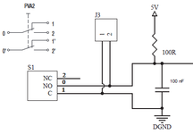
The idea is to add another (ON)-(ON) momentary switch in parallel to the PCB switch, so I can control the covnerter (application code) from the bench or panel. This is for START, STOP and RESET signals.
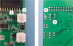
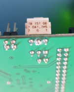
On the PCB board I have an (ON)-(ON) momentary switch S1, and next to it another input connector J3 with two pins for another switch, e.g. this one.


When running the simulation it all works as expected: both switches can change the output signal.

 www.circuitlab.com
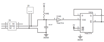
But when connecting a real external switch on J3, I do not see a change in the output signal.
Even if I add a jumper to J3, I do not see a change in the signal; i.e. output remains in the previous state.
Also, when a jumper is on J3, switch S1 doesn't change the output state.
P.S. now even when I connect S1 external pins 0 and 1, the output signal does not change.
The idea is to add another (ON)-(ON) momentary switch in parallel to the PCB switch, so I can control the covnerter (application code) from the bench or panel. This is for START, STOP and RESET signals.
On the PCB board I have an (ON)-(ON) momentary switch S1, and next to it another input connector J3 with two pins for another switch, e.g. this one.


When running the simulation it all works as expected: both switches can change the output signal.
Pushbutton v2
But when connecting a real external switch on J3, I do not see a change in the output signal.
Even if I add a jumper to J3, I do not see a change in the signal; i.e. output remains in the previous state.
Also, when a jumper is on J3, switch S1 doesn't change the output state.
P.S. now even when I connect S1 external pins 0 and 1, the output signal does not change.


