Continue to Site

Welcome to EDAboard.com

Welcome to our site! EDAboard.com is an international Electronics Discussion Forum focused on EDA software, circuits, schematics, books, theory, papers, asic, pld, 8051, DSP, Network, RF, Analog Design, PCB, Service Manuals... and a whole lot more! To participate you need to register. Registration is free. Click here to register now.

[SOLVED] DAC Converter using a PWM Modulation in VHDL

Status
Not open for further replies.

Manolitus7

Newbie level 5
Newbie level 5
Joined
Mar 9, 2022
Messages
8
Helped
0
Reputation
0
Reaction score
0
Trophy points
1
Activity points
71
Hi everyone, I'm doing an electronics project, and I'm one step away from finishing it.
The situation in which my work finds itself is as follows:
I have a set of digital data (Audio) of 16 Bits each sample, which are sampled at a certain frequency, with its corresponding flag between samples.
In order to convert that signal into audible, I need to do a PWM modulation, and filter it later.
I have searched for information about PWM modulation, where it talks about carrier and modulator signal, but I can't understand its purpose, I don't know if someone could explain to me what it consists of, and how it could be implemented in VHDL.
Thank you all.
M
 

First of all, you’re more than one step away.

Briefly, PWM modulation varies the duty cycle of a pulse train in proportion to the level of the modulating signal. At low levels the duty cycle is low; at high levels, the duty cycle is high. One way to implement PWM is to apply a triangle wave to one input of a comparator, and the modulating signal to the other input. It’s relatively simple to transfer this concept to VHDL.
 

Supposed your audio sampling rate is e.g. 44 kHz, you'll need 2.9 GHz clock frequency to achieve plain PWM with 16 Bit resolution. That can't work, at least with standard FPGA. You need some kind of resolution enhancement with high resolution PLL timer. Or use a different modulation method like sigma-delta.
 

Supposed your audio sampling rate is e.g. 44 kHz, you'll need 2.9 GHz clock frequency to achieve plain PWM with 16 Bit resolution. That can't work, at least with standard FPGA. You need some kind of resolution enhancement with high resolution PLL timer. Or use a different modulation method like sigma-delta.
The frequency of the audio signal is 8KHz. And the frequency of the PWM should be 200 KHz. How do you calculate the resolution?
thanks for answering.
 

First of all, you’re more than one step away.

Briefly, PWM modulation varies the duty cycle of a pulse train in proportion to the level of the modulating signal. At low levels the duty cycle is low; at high levels, the duty cycle is high. One way to implement PWM is to apply a triangle wave to one input of a comparator, and the modulating signal to the other input. It’s relatively simple to transfer this concept to VHDL.


Implementing a triangular wave in VHDL is not that simple, is it? I was thinking of making a square PWM, but I don't know how to mount the modulating wave on the carrier in VHDL
 

If you've got 44KHz sample frequency (nominal for audio), and you need 16-bit resolution (65536 discrete levels), then you need to break one cycle of 44KHz into 65536 different pulse widths==> 65536 x 44000 =2.88GHz. As FvM points out, this is not really feasible in an FPGA. And a 200kHz frequency is even more unfeasible.

Don't think of an analog triangle wave; think of a linearly increasing/decreasing number. The output of the comparator (your PWM) is still a square wave. Think of it this way: you've got a signal that is incremented at some high clock rate from zero to 65535 and then back to zero. You compare this reference signal to the value of your modulating signal. When the modulating signal is higher than the reference, the output is logic 1; when it's below the reference the output is logic 0.
 
The freq that you have when you attempt to implement the PWM like that is 2 * 2^adc_resolution * audio_sample_rate. For your 8k audio sample rate and 16 bit resolution, you have 2*(2^16)*8000 = 1.048576e9 Hz. There are two concerns here. One, switching your power stage at this calculated freq. Two, the audio signal inherently comes with white noise from the sampling. This white noise can be heard over the speaker. As for you mentioning modulation, PWM is a form of modulation already. The carrier being either a sawtooth or a triangle wave, which can be plemented by a an up counter or an up-down counter, respectively. But as you can see, PWM by itself is not sufficient for audio processing because of the inherent white noise that comes with sampling. You need to get the (unwanted) white noise separated from your (wanted) audio signal. Noise Shaper is one way to carry out this separation.

Research into Delta-Sigma Modulation and there lies your solution.
 
Simple calculation, consider 200 MHz FPGA clock frequency (feasible for newer families with well considered coding of the PWM logic), 200 kHz PWM => resolution 1000 steps, about 10 bits. A SD modulator for one or multiple LSB can achieve noise shaping and increase SNR for the audio band.
 
If you've got 44KHz sample frequency (nominal for audio), and you need 16-bit resolution (65536 discrete levels), then you need to break one cycle of 44KHz into 65536 different pulse widths==> 65536 x 44000 =2.88GHz. As FvM points out, this is not really feasible in an FPGA. And a 200kHz frequency is even more unfeasible.

Don't think of an analog triangle wave; think of a linearly increasing/decreasing number. The output of the comparator (your PWM) is still a square wave. Think of it this way: you've got a signal that is incremented at some high clock rate from zero to 65535 and then back to zero. You compare this reference signal to the value of your modulating signal. When the modulating signal is higher than the reference, the output is logic 1; when it's below the reference the output is logic 0.

Ok, I understand that by that logic, with a sample rate of 8kHz and a PWM of 200kHz, I get 25 discrete levels.
My "triangular signal" would be represented with 5 Bits, and would count from 0 to 24. My question is: If I have samples of several bits (64 Bits p.e.), which vary between 0 and 1, at what level of the triangle signal would the comparator trig?
--- Updated ---

Simple calculation, consider 200 MHz FPGA clock frequency (feasible for newer families with well considered coding of the PWM logic), 200 kHz PWM => resolution 1000 steps, about 10 bits. A SD modulator for one or multiple LSB can achieve noise shaping and increase SNR for the audio band.
But I don´t undertand why Akanimo calculated the resolution of the ADC with the freq of the modulation wave, and now you calculate the resolution with the FPGA clock, wich in my case is 100 MHz.
 
Last edited:

Hi,

I think there is a misunderstanding. Please clarify:

200kHz = PWM frequency. If so, then this represents the (DAC) sampling frequency.
8kHz is the analog signal that you want to reproduce with the PWM method.
What´s your idea with the "triangular signal"?
Always more useful than many words: draw a sketch

***
There is a big differnce between a typical DAC and a PWM.
For quiet AC (audio) signals the typical DAC output is almost flat, just includes some steps with tiny stepsize.
But the same signal with a PWM means a full swing 50% duty cyle square wave. This needs to be filtered to become a "quiet AC signal". It´s much more problematic for a filter to suppress the 200kHz fundamental of the full swing PWM.

If you want just a PWM, then I´d go the other way round: What is the maximum frequency you can run a binary counter in your FPGA? This is your upper limit. use this to calculate PWM resolution.

(unless you don´t want to switch to external DACs or multi-bit output)

Klaus

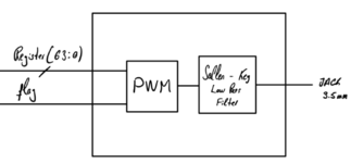
Here is the design that I have to do.
I have managed to have a shift register that "samples" every 8 kHz, and warns on each sample with a flag.
I must perform a PWM modulation at 200 kHz and then filter the message in a low pass filter that is integrated on the board.
The frequency of the board is 100 MHz. I would really appreciate if you could recommend a video or web page that explains this procedure (PWM Modulation), or if someone could explain it to me, it would be perfect.
 

Attachments

  • PWM.PNG
    PWM.PNG
    75.5 KB · Views: 185

Hi everyone, I'm doing an electronics project, and I'm one step away from finishing it.
The situation in which my work finds itself is as follows:
I have a set of digital data (Audio) of 16 Bits each sample, which are sampled at a certain frequency, with its corresponding flag between samples.
In order to convert that signal into audible, I need to do a PWM modulation, and filter it later.
I have searched for information about PWM modulation, where it talks about carrier and modulator signal, but I can't understand its purpose, I don't know if someone could explain to me what it consists of, and how it could be implemented in VHDL.
Thank you all.
M
Hello,

maybe you should consider using a low-cost Delta-Sigma DAC with I2S protocol (i mean external IC). See this link:
https://diyi0t.com/i2s-sound-tutorial-for-esp32/

In this article you have timing diagram of I2S protocol. Writing a code in VHDL for such easy protocol is easy.
And here you have links for few ICs (DAC):
https://datasheets.maximintegrated.com/en/ds/MAX5556.pdf

https://www.ti.com/lit/ds/symlink/l...l=https%3A%2F%2Fwww.ti.com%2Fproduct%2FLM4921

https://datasheets.maximintegrated.com/en/ds/MAX9880A.pdf


Best regards
 

Hi,

you text confuses me even more.
I don´t know where the 64 bit in the picture come from.

****
So I can give just an answer to what Í think I understand.

If you want to build a 200kHz PWM from a 100MHz clock,
then you need to design a binary counter counting from 0 to 499 (500 steps = 9 bits)
100MHz / 500 = 200,000 Hz
then you need to scale down your digital PWM input to a range of 0...499 (9 bits)
then feed both signals (9 bit counter, + 9 bit PWM input to a 9 bit comparator.
The output of the comaparator (">" or "<") is the PWM signal.

That´s it. basically.

Btw:
an internet search "how to generate PWM with an FPGA" gives 700,000 results, including videos.
I guess most of them use very similar technique.

Klaus
 

BTW: if you insist to use PWM modulation there are few IP cores for that on Opencores.org:

https://opencores.org/projects/wbpwmaudio

https://opencores.org/projects/pwm_with_dithering

https://opencores.org/projects/pwm

https://opencores.org/projects/ptc

Best Regards
--- Updated ---

Hi everyone, I'm doing an electronics project, and I'm one step away from finishing it.
The situation in which my work finds itself is as follows:
I have a set of digital data (Audio) of 16 Bits each sample, which are sampled at a certain frequency, with its corresponding flag between samples.
M
Hello,

Have these samples been got with analog/digital anti-aliasing filter low pass filter)? If not, it might occur distortion of signal during digital to analog processing on DAC.

Regards
 
Last edited:

Hi,

you text confuses me even more.
I don´t know where the 64 bit in the picture come from.

Klaus
Hi,

The samples have a size of 16 Bits (2 Bytes) each. If the register has a size of 64 Bits, it is because it has received 4 Samples. They are saved by the shift register, accompanied by a write flag. They come from a RAM memory controlled by a state machine.

Hello,

Have these samples been got with analog/digital anti-aliasing filter low pass filter)? If not, it might occur distortion of signal during digital to analog processing on DAC.

Regards
Hi,

Filtering has to be done after modulation, according to design specifications.
 
Last edited by a moderator:

Ok, I understand that by that logic, with a sample rate of 8kHz and a PWM of 200kHz, I get 25 discrete levels.
My "triangular signal" would be represented with 5 Bits, and would count from 0 to 24. My question is: If I have samples of several bits (64 Bits p.e.), which vary between 0 and 1, at what level of the triangle signal would the comparator trig?
--- Updated ---
No.

First of all, as pointed out in several posts, a triangle wave based PWM is not feasible for your requirements.

Secondly, the sample rate of your input signal has nothing to do with the number of levels in your PWM. Again, it’s a function of your resolution (you said 16 bits).

The output of the comparator will ’trigger‘ when the value of the input signal crosses the value of the triangle signal.
 
Hello @Manolitus7,

with these shift registers you are trying to make serial protocol which is very similiar to existing standard I2S protocol. You concept to use PWM modulation is not optimal, the better way is using external Delta-Sigma DAC (IC). See these links:

https://www.allaboutcircuits.com/te...-the-delta-sigma-analog-to-digital-converter/

https://www.allaboutcircuits.com/news/ctsd-adcs-alias-free-adc/

It is easier to use such DAC in your project, then making DAC with PWM by your own.

Best Regards
 

The freq that you have when you attempt to implement the PWM like that is 2 * 2^adc_resolution * audio_sample_rate. For your 8k audio sample rate and 16 bit resolution, you have 2*(2^16)*8000 = 1.048576e9 Hz. There are two concerns here. One, switching your power stage at this calculated freq. Two, the audio signal inherently comes with white noise from the sampling. This white noise can be heard over the speaker. As for you mentioning modulation, PWM is a form of modulation already. The carrier being either a sawtooth or a triangle wave, which can be plemented by a an up counter or an up-down counter, respectively. But as you can see, PWM by itself is not sufficient for audio processing because of the inherent white noise that comes with sampling. You need to get the (unwanted) white noise separated from your (wanted) audio signal. Noise Shaper is one way to carry out this separation.

Research into Delta-Sigma Modulation and there lies your solution.
If your audio data has a resolution of 16 bits, then you need a minimum of 16 bits counter to be able to compare every possible value of the audio samples. So if you have a 16-bit counter, in order to produce a triangle wave, you need to count 2^16 steps upwards to go from zero to the peak of the triangle wave and 2^16 step downwards to get back to zero. So this counting up and then down produces one period of the triangle wave. Every successive period of the triangle wave, you process a successive sample of the audio data. So if you have audio data with 8k sample rate, then you need a frequency of 2*(2^16 steps) * 8k samples = 1.048576e9 Hz. This however will generate an 8k PWM frequency. To generate a 200k PWM frequency, you need to interpolate the 8k audio samples by 25 times. This gives a clock frequency of 2*(2^16 steps)*8k*25 = 2.62144e10 Hz. That's over 26 GHz.

So post #7 was for 8 kHz PWM frequency and 1.048576e9 Hz internal clock frequency.

Delta-Sigma modulator comes in handy here to both reduce the internal clock frequency and to separate white noise from the audio.
 
Status
Not open for further replies.

Similar threads

Part and Inventory Search

Welcome to EDABoard.com

Sponsor

Back
Top