Continue to Site

Welcome to EDAboard.com

Welcome to our site! EDAboard.com is an international Electronics Discussion Forum focused on EDA software, circuits, schematics, books, theory, papers, asic, pld, 8051, DSP, Network, RF, Analog Design, PCB, Service Manuals... and a whole lot more! To participate you need to register. Registration is free. Click here to register now.

[SOLVED] 4 Stage feedforward amplifier design question on phase dip

Status
Not open for further replies.

jgk2004

Full Member level 5
Full Member level 5
Joined
Dec 1, 2009
Messages
274
Helped
77
Reputation
154
Reaction score
74
Trophy points
1,308
Location
Munich Germany
Visit site
Activity points
3,520
Hello all,

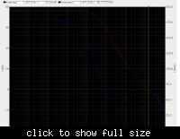
I am designing a 4 stage feedforward compensated amplifier and I am seeing a phase dip, see attached. I am wondering what people commonly consider reasonable dip when design 4 or higher stage amplifiers. Over all i am always above 40degrees. Also this amplifier will not be used as a follower but as an integrator, so i feel i shouldn't have a probem with instability.. What do you guys think?


Jgk
 

Hi John,

just a practical hint: simulate your amp within its application environment, i.e. as integrator, perhaps with artificial parasitics to be expected from layout. For w.c. use a steep step edge and see if you notice some ringing in the low phase margin frequency range. Even if so, it probably won't hurt.

erikl
 

Hi Erikl,

I have already done this and I do not see anything in the time domain. I have also added expected parasitics and have seen no change as well. I just wanted to double check with the edaboard to see if anyone else has made one of these before and seen a similar PM and had problems with there measured performance. Have you made one before?

Jgk
 

Hi Jgk,

I think, you shouldn't expect any problems using the shown circuit (resp. its Bode diagram) for amplifier or integrator applications.
Its quite normal that the phase goes up again if the gain slope changes from -40 to -20 dB/dec.
More than that, this phase increase is the only reason for this slope decrease.
 

Be aware that such a dip is caused by a pole/zero doublet so you will have a slow settling component to your circuit.
 

Yes that is true, but I still have a fast part within the two stages to the output. I would only have the doublet when looking through all 4 stages. So I would say I shouldn't have a problem with settling.
Jgk
 

Yes that is true, but I still have a fast part within the two stages to the output. I would only have the doublet when looking through all 4 stages. So I would say I shouldn't have a problem with settling.
Jgk
I don't understand how the zero that is used to offset the pole won't affect your settling. Can you elaborate?

rg
 

Sure!

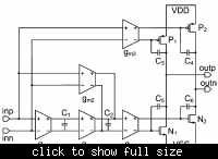
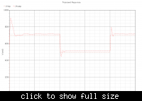
When looking at the attached figure there is a path to the output which doesn't have the pole zero doublet, 2 stage path on the top, 3 stage in the middle, 4 stage on the bottom, thus you will still have fast settling. I have attached a tran of the amplifier.


Jgk
 

Status
Not open for further replies.

Part and Inventory Search

Welcome to EDABoard.com

Sponsor

Back
Top