Jester
Full Member level 6

I'm routing a 4 layer board with a USB2.0 differential pair.
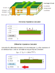
The application note has an example stackup for a 4 layer FR-4 board as shown below (top image). The example includes trace width and spacing for a 90Ω differential pair.
When I enter these parameters into either of the calculators I have, they both give the same result of about 103Ω, also shown below.
Both calculators I have show the stackup as a 2 layer board, however I would think (perhaps incorrectly) that additional layers below what is shown would have minimal impact on the impedance of the traces above the ground plane, but perhaps this is a faulty assumption?
Can anyone explain the 90Ω vs. 103Ω discrepancy?
If the discrepancy is as a result of the 4 layers stackup vs. the 2 layer stackup shown in the calculator, does anyone have a link to a calculator where I can enter all the required parameters for a board as shown in the top image?


