Continue to Site

Welcome to EDAboard.com

Welcome to our site! EDAboard.com is an international Electronics Discussion Forum focused on EDA software, circuits, schematics, books, theory, papers, asic, pld, 8051, DSP, Network, RF, Analog Design, PCB, Service Manuals... and a whole lot more! To participate you need to register. Registration is free. Click here to register now.

3x3mm vs 5x6mm SMD FETs for SMPS.

cupoftea

Advanced Member level 5
Joined
Jun 13, 2021
Messages
2,930
Helped
59
Reputation
118
Reaction score
134
Trophy points
63
Activity points
15,518
Hi,
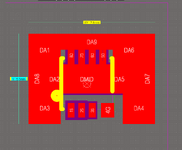
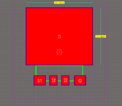
As you know smd fets come in mostly either 3x3mm or 5x6mm packages.
If they both occupy the same PCB area, with copper pour around the package,
then the 3x3mm will always run cooler (other things being equal), since it will
have more exposed PCB copper.
So why do they not advertise this on the datasheet?
 
Different applications have different needs. To compare the temperatures of 2 different FETs, you need to also ensure that other parameters are the same. If you are in an application that is primarily conduction-loss constrained, if your 3x3mm component has substantially larger resistance than a comparably priced 5x6mm component, then the latter might still run much cooler.

For comparison, let's look at these 2 60V MOSFETs that are similarly priced on Digikey:

Note that the 5x6mm part has almost half the on-state resistance.

Furthermore, the 5x6mm part has less than half the thermal resistance with both parts having about the same cooling area on the PCB - from the datasheet.

Obviously, we're picking different parts but my point is that the larger part might be the clearly better. Obviously there are other considerations like packaging requirements, etc. You specify "other things being equal" but that's not necessarily true. You could probably find two parts that will show you the opposite case and confirm your point but, again, depends on what parts you pick.
 
Thanks, if rdson and Qgd, Qgs , Qg , Rthjc, are all equal, then the 3x3mm will run cooler than the 5x6mm....given that they have the same cooling copper area....the disadvantage of the 5x6mm is that it sits over more of its cooling copper and so conceals it from air convection currents.
Its 3x3mm all the way, you concur?
 
If heat throw is vertical then bigger is better. If 5x6 has a
full body metal lid then cooling might be as good as the
unused area around 3x3, turned to copper. But if 5x6 has
the same 2x2mm die as a 3x3 then no, vertical conduction
is probably not improved as package bottom is thin and
lateral conduction in it, often not significant. If 5x6 has a
bigger die than 3x3 then the same input power would be
spread better from the start.

These kinds of "which is better?" questions couched in odd
and incomplete snippets of theory are no match for a little
bench work.
 
Thanks, i would wonder if say, 3x3 was better than 5x6, but then would different fets of that size comply to that aswell?....ie, if one 3x3, is better than one 5x6, what about others.
 
If they both occupy the same PCB area, with copper pour around the package,
then the 3x3mm will always run cooler (other things being equal), since it will
have more exposed PCB copper.
Seems like the condiderations start with erroneous reasoning.
Heat is dissipated by top surface (copper + transistor package), bottom surface and a smaller extent by horizontal spreading through ground plane. Why should Rth package to ambient be smaller with 3×3 package if occupied total area is the same?
 
Why should Rth package to ambient be smaller with 3×3 package if occupied total area is the same?
Thnaks...because less of the copper pour is covered up by the 3x3 fet. So it is more free to convect heat away. The body of the 5x6 fet covers up the copper beneath it.
 
Hi,

copper is used to spread the heat to a wider area. But copper is not in first place used to transfer the heat to the ambient air.

This means, even if there is a plastic package it istill is useful to transfer the heat to the air. And the package surely increases the surface.
It acts a little like fins on heatsinks.
I guess that the "uneven" surface of a package also improves heat transfer in "non laboratory" conditions. I mean in laboratory one has rather controlled conditions in the meaning of air flow direction, uniformity and speed.
In realit this is different.

Klaus


Attachments

  • ____3X3 NFET.png
    ____3X3 NFET.png
    37.9 KB · Views: 38
  • ____5X6 NFET.png
    ____5X6 NFET.png
    25.8 KB · Views: 32
It's quite a stretch when you say that it's "obvious" the 3x3 will run cooler. Even with the two parts shown, consider that the 3x3mm part has a substantially larger junction-to-case thermal resistance (>4x). So your junction could be at a higher temperature even if the case is at a cooler temperature, compared to the 5x6mm part.
 
The vast majority of heat leaves the copper pad through conduction via the rest of the PCB, rather than convection above the copper pad.

Try carrying your logic to the extreme. As power dissipation becomes more concentrated over a smaller area (like 1mm2, or 0.1mm2), device temperature must increase.
 

LaTeX Commands Quick-Menu:

Similar threads

Part and Inventory Search

Welcome to EDABoard.com

Sponsor

Back
Top