Continue to Site

Welcome to EDAboard.com

Welcome to our site! EDAboard.com is an international Electronics Discussion Forum focused on EDA software, circuits, schematics, books, theory, papers, asic, pld, 8051, DSP, Network, RF, Analog Design, PCB, Service Manuals... and a whole lot more! To participate you need to register. Registration is free. Click here to register now.

High Current Inductance Design and Saturation Problem

Status
Not open for further replies.

Yakup

Newbie
Newbie level 3
Joined
Dec 17, 2020
Messages
4
Helped
0
Reputation
0
Reaction score
0
Trophy points
1
Activity points
31
Hi everyone, I need a powerful inductor for LC filter working at 400V, 20Khz, 12Amp, 1300uH. I was bought some core for design it. But it doesn't work because saturation problem. Then I have researched again and I refigured. I learned that I needed iron powder cores because of their low Al values. But even though I can find them online, it is really difficult to buy them. Because I cannot find a core with the values I need in any electronics supplier. How do you solve this situation, what do you suggest me for this? For example, would I run into a problem if I use high Al ferrite cores in parallel to reduce the current?
 

Can you try Magnetics incorporated. (Mag Inc)
Or maybe the makers of Sendust.
Or Kool Mu (i think its called)
 

Hi Yakup,


If you not able to buy low AL value core,Buy EE core or any other supporting 20KHz.

Create air gap between core halves so that the AL value will come down.Saturation for a core will come down with suitable number of turns.

For 1300uH,12A E71/33/32-3C90-E100 from FXC will be suitable
No. of turns:115
Bmax:0.2T

If you not able to procure E71/33/32-3C90-E100,Buy E71/33/32-3C94 from below link and grind the centre leg for air gap.

Link:https://www.digikey.in/product-detail/en/ferroxcube/E71-33-32-3C94/1779-1063-ND/7041523


Selvam
 
  • Like
Reactions: Yakup

    Yakup

    Points: 2
    Helpful Answer Positive Rating
20Khz, 12Amp Ac rms, 1300uH, peak storage = 0.5 L Ipk^2 = 0.5 1.3mH 17^2 = 188mJ

= 0.5 (B^2 / Ugap) . Volgap, so for peak B of 280mT, and Ae = 370mm^2 ( PM 50 / 39 core ) and Ugap = 4.pi.E-7

we get Lgap = 16.27mm and AL = 28.56 nH / T^2 thus 148 turns,

the bobbin has only 154m^2 space, hence only room for 1mm diameter which will not carry 12A ac

So next size up: PM74/59 Ae = 790mm^2, so Lgap = 7.62mm ( 3.85 mm right thru )

So AL = 130.3 nH/T^2, giving N = 99 turns, giving a max wire size of 1.2mm dia - not really going to carry 12A ac either

So, 2 x PM74/59 in parallel, 8.5Apk, 2.6mH, Epk = 93.9mJ, thus Lgap = 3.8mm ( 1.9mm right thru ), and AL = 261.2 nH / T^2

and N = 310 @ 6 A rms, 0.7 mm dia R = rho. L / Aw, = 17.E-9 x 310 x MLT(140mm) / 0.384 mm^2 = 1.92 ohm @ 25 degC

= 70 watts => no good,

time for a really big core, say we go for the E71/33/32, using 4 cores, 2 sets in parallel, Ae = 1366mm^2, for 17Apk, 1.3mH,

we get for Lg = 4.4mm ( 2.2mm right thru - i.e. each leg ) and AL = 390 nH/T^2, giving N = 52 turns

Winding area = 570mm^2 this allows 10mm^2 per turn = 3mm dia max, easily enough for 12A ac rms

MLT is about 220mm, so 52 turns gives 11.5m of wire, for a dissipation of 10 watts, R = 69 m-ohms = rho. L / Aw

hence Aw must be >= 2.84 mm^2 or 1.9 dia - so an easy fit.
 
  • Like
Reactions: Yakup

    Yakup

    Points: 2
    Helpful Answer Positive Rating

    Velkarn

    Points: 2
    Helpful Answer Positive Rating
20Khz, 12Amp Ac rms, 1300uH, peak storage = 0.5 L Ipk^2 = 0.5 1.3mH 17^2 = 188mJ

= 0.5 (B^2 / Ugap) . Volgap, so for peak B of 280mT, and Ae = 370mm^2 ( PM 50 / 39 core ) and Ugap = 4.pi.E-7

we get Lgap = 16.27mm and AL = 28.56 nH / T^2 thus 148 turns,

the bobbin has only 154m^2 space, hence only room for 1mm diameter which will not carry 12A ac

So next size up: PM74/59 Ae = 790mm^2, so Lgap = 7.62mm ( 3.85 mm right thru )

So AL = 130.3 nH/T^2, giving N = 99 turns, giving a max wire size of 1.2mm dia - not really going to carry 12A ac either

So, 2 x PM74/59 in parallel, 8.5Apk, 2.6mH, Epk = 93.9mJ, thus Lgap = 3.8mm ( 1.9mm right thru ), and AL = 261.2 nH / T^2

and N = 310 @ 6 A rms, 0.7 mm dia R = rho. L / Aw, = 17.E-9 x 310 x MLT(140mm) / 0.384 mm^2 = 1.92 ohm @ 25 degC

= 70 watts => no good,

time for a really big core, say we go for the E71/33/32, using 4 cores, 2 sets in parallel, Ae = 1366mm^2, for 17Apk, 1.3mH,

we get for Lg = 4.4mm ( 2.2mm right thru - i.e. each leg ) and AL = 390 nH/T^2, giving N = 52 turns

Winding area = 570mm^2 this allows 10mm^2 per turn = 3mm dia max, easily enough for 12A ac rms

MLT is about 220mm, so 52 turns gives 11.5m of wire, for a dissipation of 10 watts, R = 69 m-ohms = rho. L / Aw

hence Aw must be >= 2.84 mm^2 or 1.9 dia - so an easy fit.


I have that core (following pdf document) little bit small than E71/33/32. Do you think this core can help me with air gap, I have 4 E core (2 EƎ) .
Sorry, could you please recalculate for this core, if it is not too difficult for you?


Edit: https://coil32.net/online-calculators/e-core-calculator.html This web site can calculate with Air Gap and give me Max Current and Number of turns. Can I rely this solutions?

1620036542634.png
 

Attachments

  • CF139 EE6527.pdf
    92.6 KB · Views: 113
Last edited:

Basically, your equation of interest, is i(SAT) = B.A.N/L
where B = saturation mag flux density (ie 0.3T), A = Area

It seems that your application is an inverter, and your inductor must not saturate at 12A *SQRT(2).
...Then add another 20% on top of this for the ripple current....so thats 20.36A peak in your case.

Taking the TDK E70/33/32 core and using MDT tool software (free download), then we see that one core set with 3.5mm gap gives AL = 240.
Thus 74 turns gives your 1.3mH.
With 2 such core sets stuck together , The saturation current is (from above equn) 23.3A so thats OK.

So now we see what diam of wire we can get into the winding area available..The winding area is 572mm^2
So the wire can be up to 7.7mm^2
Thats 2.46mm diam wire
With two E70/33/32 cores stuck together, your Mean length of turn is 224mm

Now we need some resistance/metre tables for Litz wire thats ~2.46mm in diam.

Also, we also need a graph of core loss versus B for N87 ferrite material (and at 20kHz) , so we can check your delta B losses are not too high.

You will need to add some packing tape at the inside of the core so that the windings are not too near the core gap.
 
Last edited by a moderator:
  • Like
Reactions: Yakup

    Yakup

    Points: 2
    Helpful Answer Positive Rating
Basically, your equation of interest, is i(SAT) = B.A.N/L
where B = saturation mag flux density (ie 0.3T), A = Area

It seems that your application is an inverter, and your inductor must not saturate at 12A *SQRT(2).
...Then add another 20% on top of this for the ripple current....so thats 20.36A peak in your case.

Taking the TDK E70/33/32 core and using MDT tool software (free download), then we see that one core set with 3.5mm gap gives AL = 240.
Thus 74 turns gives your 1.3mH.
With 2 such core sets stuck together , The saturation current is (from above equn) 23.3A so thats OK.

So now we see what diam of wire we can get into the winding area available..The winding area is 572mm^2
So the wire can be up to 7.7mm^2
Thats 2.46mm diam wire
With two E70/33/32 cores stuck together, your Mean length of turn is 224mm

Now we need some resistance/metre tables for Litz wire thats ~2.46mm in diam.

Also, we also need a graph of core loss versus B for N87 ferrite material (and at 20kHz) , so we can check your delta B losses are not too high.

You will need to add some packing tape at the inside of the core so that the windings are not too near the core gap.

Thanks to all of you. Every posts was really helpful for me. I think it's the time of experience. I will make an inductor and share results with you.
 

Hi everyone, I need a powerful inductor for LC filter working at 400V, 20Khz, 12Amp, 1300uH. I was bought some core for design it. But it doesn't work because saturation problem. Then I have researched again and I refigured. I learned that I needed iron powder cores because of their low Al values. But even though I can find them online, it is really difficult to buy them. Because I cannot find a core with the values I need in any electronics supplier. How do you solve this situation, what do you suggest me for this? For example, would I run into a problem if I use high Al ferrite cores in parallel to reduce the current?
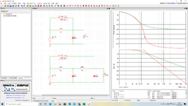
Add a stage to your filter which will lower the inductance giving you many more options for higher currents
 

I don't understand. What stage should I add, for example?
Its just a consideration. A single stage LC filter will give you a 40db per decade roll off, if you add a second stage of LC filtering it will go to 80db/decade and to get the same level of filtering you will require smaller values of L & C which will give you higher saturation currents and higher component SRF than what you would get with a single larger part. Its more parts and the resonances at lighter loads may require some attention but its a viable option in some cases. I attach an example based on the Voltage and Current you mentioned with a 20db Attenuation @ 20khz.
 

Attachments

  • 1v2 stage.png
    1v2 stage.png
    208.7 KB · Views: 155

S0, the core you propose has a centre pole of 20 x 27.4 mm x 2 sets of cores ( 4 cores ) = 1096 mm^2

so the gap will be 4.4mm x 1366 / 1096 = 5.48mm

and the AL will be = Uo . Ae /Lg = 251.2 nH / T^2 => so N = 70 Turns

The winding area is 44 x 12 = 528mm^2 / 70 = 7.54mm^2 per turn max, = 2.5mm dia max - so OK for 12A rms

because the winding itself will have some inductance without the cores, you can wind 70 Turns, gap right thru at 2.7mm in each leg, and then remove turns until you are close to 1.3mH - or simply increase the gap a wee bit to get 1.3mH <- this will give you more peak current capability.

[ Design is for B = 0.28T @ 17Apk ]
--- Updated ---

@scopeprobe: Add a stage to your filter which will lower the inductance giving you many more options for higher currents
the problem here is the peak currents and ripple are quite a bit higher in the 1st stage - than for the single stage filter

thus the choke in the 1st stage must be carefully designed for the flux ripple and extra losses that can occur - i.e. it must be of significantly higher Q, similarly the cap in the 1st stage must be able to handle more ripple current - i.e. it's Q must be very good too.

Single stage - although with a more sluggish roll off - overcomes these issues.
 
Last edited:

Status
Not open for further replies.

Similar threads

Part and Inventory Search

Welcome to EDABoard.com

Sponsor

Back
Top