Continue to Site

Welcome to EDAboard.com

Welcome to our site! EDAboard.com is an international Electronics Discussion Forum focused on EDA software, circuits, schematics, books, theory, papers, asic, pld, 8051, DSP, Network, RF, Analog Design, PCB, Service Manuals... and a whole lot more! To participate you need to register. Registration is free. Click here to register now.

Commodore 1084s monitor with faint vertical lines

Status
Not open for further replies.

fbone

Newbie level 6
Newbie level 6
Joined
Dec 15, 2020
Messages
13
Helped
1
Reputation
2
Reaction score
3
Trophy points
3
Activity points
109
Hi guys!

First of all what a great forum! Also Happy New Year to all :)

I need your help with my monitor which produces faint vetical lines at the left side of the screen (image attached)

1084s vertical lines.jpeg.

I read some great tips and info in this thread and I created my own not to hijack that one! (https://www.edaboard.com/threads/he...with-my-commodore-1084s-p-crt-monitor.393932/)

Please guide me if you suspect the culprit. I have already recapped this monitor and replaced HOT as a preventive step.

Thank you in advance!

George
 

Hi,

Many years ago I worked at a monitor repair.
There may be many reasons for this behaviour.
One - I remember - was when the picture adjustment was too much at the left side.
May be try the horizontal adjustment.

Do you use a short, good quality signal cable? Maybe try different cables to see if there is a change..

Klaus
 
  • Like
Reactions: fbone

    fbone

    Points: 2
    Helpful Answer Positive Rating
thank you Klaus!

I think it must be something else since the monitor works properly with image.. I just took this photo without something else showing to make the lines more obvious. When the monitor operates the lines are barely noticable..
 

Hello fbone,
My apologies for this late reply.
Could I please get you to take a screen picture with a proper static image?
I'll also get you to measure the 12 volt rails.
(1) +12 at Pin 3 of IC 403
(2) +12A at the junction of SK2 and R232
(3) +12C at the junction of R562 and C562

Regards,
Relayer
 

    fbone

    Points: 2
    Helpful Answer Positive Rating
I remember a very similar fault on a Philips G8 television; it was 5th harmonic oscillation on the line linearity coil caused by the 1K5 1W dampening resistor in parallel with the coil being open circuit. It may be worth while looking at the line linearity coil dampening resistor.
 

    fbone

    Points: 2
    Helpful Answer Positive Rating
thank you both for your answers and time! I will open up the monitor this coming week and come back with more information!
 

On the 1084 the resistor across the line linearity coil is R472 1K. Check out of circuit to see if it is high in value.
 

hi guys!

I have some answers..

pin 3 of IC403 is 12V, at SK2 also 12V, could'nt find R562. Also R472 is measuring 1K..

the main psu outputs 125V, 16V, 26V at the 4-pin connector.

I noticed today that except the vertical lines that indeed look like some harmonics as they repeat and further fade towards the middle of the screen, there seems to be some horizontal noise in the form of VERY faint pencil-thick lines the go from top to bottom. Barely noticable but they are there and move slowly towards the bottom of the screen.

dont think they are very well captured in the photos.. while the 1st vertical line is clearly seen in pic3.

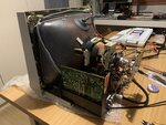
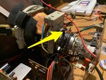
secondary question: Convergence rings come to three sets of two, what it the big single ring in front of them (a 7th ring).. couldn't find an explanation online (pics 4-5).

2021-01-14_00-52-43.jpg2021-01-14_00-53-16.jpg2021-01-14_01-02-10.jpgjpeg_2021-01-14_01-17-02_1.jpegjpeg_2021-01-14_01-17-02_2.jpeg
--- Updated ---

Just found C562/R562 at 11.80V (60' passed so I couldn't edit previous message)
 
Last edited:

It seems all the 12 volt rails are spot on.
Same goes for the PSU voltages.
What ever you do, DON'T touch the convergence rings. They are definitely not part of the problem.
If you're having doubts about convergence, then you'll need a cross-hatch pattern generated to see
any misconvergence.

there seems to be some horizontal noise in the form of VERY faint pencil-thick lines the go from top to bottom.

That could be due to your main filter capacitor (C112) having lost some of it's capacitance.
The best way of confirming this is to place, say a 100uF 400V capacitor in parallel with it to see if anything changes.
Remember, what ever cap you may tack across it, must be an electrolytic and most importantly is rated at 400 volts.
The other alternative is to replace the cap with a new one.
This may also contribute to the vertical lines.

If you have a capacitance and an ESR meter, I'll get you to check the following caps:
C461 (2.2uF 63V)
C462 (22uF 40V)

Please let us know how you get on.
Regards,
Relayer

P.S. Did you try pjmelect's suggestion?
On the 1084 the resistor across the line linearity coil is R472 1K. Check out of circuit to see if it is high in value.
 

hi @Relayer! thank you for your input. I have recently recapped the monitor and PSU replacing ALL electrolutics. I have also measured R472 to be 1k as it should.

I will double-check of course.

Regarding the convergence rings I am not planning to touching them (yet! :D) but I would like to know what the first big ring in front of them is.
 

The ringing is definitely in the line output stage, you don’t need to look any where else for the cause. It looks to me that the ringing is caused by an inductor (maybe the line output transformer itself) discharging, and that a dampening resistor across the inductor being high or open circuit, check all resistors in the line output stage.
 

    fbone

    Points: 2
    Helpful Answer Positive Rating
ok @pjmelect! will do that and come back. Could it also be a h-hold or v-hold pot??
 

I would like to know what the first big ring in front of them is.

The ring you've shown by the yellow arrow is the locking ring. It locks the convergence rings in
place and prevents them from being accidentally moved.

I have to agree with pjmelect that the fault is in the line output stage.

It looks to me that the ringing is caused by an inductor

I would also look at some non-polarised capacitors in the line output stage for drift in
capacitance.
Also do a thorough test on the damper diodes D467 and D468.

Let us know how you get on.
Regards,
Relayer
 

hi again!

-= bonus info and question on locking ring =-: I think someone has messed with the convergence rings before so I might have to play around later on. Regarding the "locking ring", I guess it doesn't play a role in the electron beams right? will it matter if its rotated or not?

I also tried to find the damper diodes D467 and D468 but could not locate them.. I attached the schematic which corresponds to my PCB incase that helps pinpoint those (high quality scan I found online).

In the meantime I measured R348 to be 560ohm as expected. R461 measures 500ohm instead of 1K but thats in-circuit, I am dead meat so Ill measure it disconnected tomorrow (2.35am here ATM).

I also checked all other diodes that I could find and seem to be ok.

Maybe a helpfull observation (revisiting first post) is that the vertical line is also visible WITHOUT input signal i.e. the monitor powered on (dark screen) but the Amiga 500 attached to it powered off.

you guys mentioned "line output stage", is that the output from the horizontal and vertical ICs to the yoke deflection coils? should I measure ALL related resistors as @pjmelect mentioned or are there some more important ones?

I hereby attach a link that seems to be the OCR text of the schematics: https://archive.org/stream/philipscm8833sm/philipscm8833sm_djvu.txt

thank you guys for the time you put into this I really appreciate it.
 

Attachments

  • Philips_CM8833_Service_Manual_scanned_by_Gona_PDF_by_Guru.pdf
    67.7 MB · Views: 217

will it matter if its rotated or not

It's risky for two reasons. Those rings are located where the glass is thin. They may be clamped or glued. They're probably hard to move and you might break the glass if you try.

For another thing a color monitor has 3 beams to keep aligned. An attempt at adjustment can lead to misalignment which you try to cure but ends up becoming worse.
How do I know? Experience.
 

    horttanainen

    Points: 2
    Helpful Answer Positive Rating

    fbone

    Points: 2
    Helpful Answer Positive Rating
I also tried to find the damper diodes D467 and D468 but could not locate them

That's strange that you couldn't find those diodes.
Could you please let me know what is the exact part number of the horizontal output transistor.
You need to physically look at the part.

An attempt at adjustment can lead to misalignment which you try to cure but ends up becoming worse.

I have to agree. Unless you can obtain a cross-hatch test pattern, I'd leave those rings alone.

At this point I'd like you to test the voltages around the pins of IC402, especially pins 2 and 4.
If you have an oscilloscope, it would be good to get waveform readings from waveforms 12 and 13.

Regards,
Relayer
 

I have now checked ALL diodes on the motherboard (including D467/8 ... getting more familiar with the schematics) and all seem to be ok.. couple I had to desolder and measure off-circuit.

I will be able to do more measurement this week. Can you please explain what I am expecting to see at pins 2 & 4? Also at 12 & 13? I do have an oscilloscope just need to bring the monitor at the lab.

any chance IC 402 is faulty? I am asking since Im placing an order for parts and I could include a couple of TDA2595s.
 

Can you please explain what I am expecting to see at pins 2 & 4? Also at 12 & 13?

The 12 and 13 are the waveform numbers.
Waveform 12 is the critical one. It's the horizontal out signal. You should be able to match up the waveform
with the one shown on that rail (12). I have to admit, details are not the best, but the basic shape and amplitude
you should be able to see through your scope.
Pin 4 of the IC should show waveform 17, which goes to the horizontal width control.

any chance IC 402 is faulty? I am asking since Im placing an order for parts and I could include a couple of TDA2595s.

It's possible. Though I tend to think that you have a passive component fault. A cap, inductor or a resistor.
But at this point it wouldn't hurt to replace IC402. It will at least fix the fault or it will just let us know that the IC isn't the culprit.

Regards,
Relayer
 

Definitely following this - have the exact same issue with a 1084S I'm looking at for a mate and it has defeated me thus far...
 

hi again guys! welcome psoma! still looking to solve this? hopefully we'll all manage to do this together.

just posting to say I haven't given up it was just couple of crazy weeks at work and I will get back to the monitor asap. hope you guys can wait a bit longer!
 

Status
Not open for further replies.

Part and Inventory Search

Welcome to EDABoard.com

Sponsor

Back
Top