ysba
Advanced Member level 4

Hello,
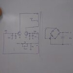
I've stumbled with the circuit in the attached image.

It is a DC-DC converter which uses a small ferrite transformer, driver by two oscillating BJT. The output is then rectified to generate a DC output voltage. It is pretty simple, works just fine. The switching frequency is about 14 kHz and the output voltage follows the DC input voltage according to the turns ratio.
Does anyone know if this circuit has a specific name? Is there some paper or documentation that explains this circuit in detail?
Thanks.
Cheers,
Yuri
- - - Updated - - -
I think I got it:
https://davidcaudrey.me.uk/page8.html
"Saturating core DC-DC converter"
If anyone has some info to add it would be nice.
Thank you very much.
I've stumbled with the circuit in the attached image.

It is a DC-DC converter which uses a small ferrite transformer, driver by two oscillating BJT. The output is then rectified to generate a DC output voltage. It is pretty simple, works just fine. The switching frequency is about 14 kHz and the output voltage follows the DC input voltage according to the turns ratio.
Does anyone know if this circuit has a specific name? Is there some paper or documentation that explains this circuit in detail?
Thanks.
Cheers,
Yuri
- - - Updated - - -
I think I got it:
https://davidcaudrey.me.uk/page8.html
"Saturating core DC-DC converter"
If anyone has some info to add it would be nice.
Thank you very much.


