Continue to Site

Welcome to EDAboard.com

Welcome to our site! EDAboard.com is an international Electronics Discussion Forum focused on EDA software, circuits, schematics, books, theory, papers, asic, pld, 8051, DSP, Network, RF, Analog Design, PCB, Service Manuals... and a whole lot more! To participate you need to register. Registration is free. Click here to register now.

Step response of fully differential amplifieer

Status
Not open for further replies.

Junus2012

Advanced Member level 5
Joined
Jan 9, 2012
Messages
1,552
Helped
47
Reputation
98
Reaction score
53
Trophy points
1,328
Location
Italy
Activity points
15,235
Dear friends,

We need a closed loop amplifer connection with a gain=unity for the purpose of simulating the large and small signal response, I usualy do by using resistor feedback with RF=Rin. However I see some people are using capacitors as a feedback elements as shown below, which one of the configuration should be preferable and what is the values of these capacitors should be ?

Thank you simulation_settling.PNG
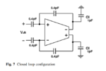
 

This is probably just a model of a switched capacitor circuit. The circuit given as is makes little sense since there is nothing to set the dc bias conditions for the inputs of the OTA.
 
This is probably just a model of a switched capacitor circuit. The circuit given as is makes little sense since there is nothing to set the dc bias conditions for the inputs of the OTA.

Thank you Suta,

but how can capacitor set the DC biasing condition when it is open in DC ?

second if I would use this configuration, the feedback capacitor will change my GBW of the amplifier under test, unless if you tell me to connect very small values comparing to the load capacitor
 

It can not set the DC op the way the circuit is drawn. If it is in a switched-capacitor context, the circuit usually works in at least two clock phases with switches involved. The first one usually samples Vin and shorts the OTA inputs to VCM. During the second phase, the circuit redistributes the charge to produce the output. In this context capacitors are charged/discharged and capacitors are like batteries. So, they get charged with respect to OTA input CMV and/or output voltage. These batteries then define the DC conditions besides the signal to the OTA.
The feedback capacitors, together with the load cap participate into the definition of the GBW of the feedback system.
 
Status
Not open for further replies.

Part and Inventory Search

Welcome to EDABoard.com

Sponsor

Back
Top