Continue to Site

Welcome to EDAboard.com

Welcome to our site! EDAboard.com is an international Electronics Discussion Forum focused on EDA software, circuits, schematics, books, theory, papers, asic, pld, 8051, DSP, Network, RF, Analog Design, PCB, Service Manuals... and a whole lot more! To participate you need to register. Registration is free. Click here to register now.

TPS54560: Voltage is dropping when load connected

Status
Not open for further replies.

vimalraj

Junior Member level 2
Joined
Apr 3, 2019
Messages
23
Helped
0
Reputation
0
Reaction score
0
Trophy points
1
Activity points
196
Hi,

I am using TPS54560 buck converter IC for my project this is the first time.

Vin=20v-60v, Vout=12V, Iout=5A, Fsw=400KHz this is my design parameter. I am getting 12.6V as output when no load is connected. After I connect 0.5A load, the output voltage is suddenly dropped to 3v.
WBDesign10 (2).jpg
I have tried many possibilities but none of it gave me a good result, at last, I am here

Kindly give me a solution

Thank you.
 

Does this happen for the entire range of input voltages? What happens with a .1A load? .25A load? Have you looked at signals with a scope? What does your layout look like?
 

is your power supply source over loaded?

- - - Updated - - -

try 470uF on the input ...!
 

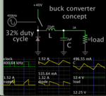
Simulation showing waveforms you can expect in a buck converter, supply 40V, load 1A @12V.

buck conv clk-driv 400kHz 40V supply 1A load at 12V.png

To obtain your spec maximum of 5A, your inductor should have a saturation rating which can handle a level 10 to 50 percent more than that.
 
Does this happen for the entire range of input voltages? What happens with a .1A load? .25A load? Have you looked at signals with a scope? What does your layout look like?

Yes it happens for entire range of input.
For 1A load, the voltage drop increases and if I further increase the load, voltage drop increases.
I have not checked with oscilloscope yet. i will upload the screenshot soon. i have no idea why it is not working after using the circuit designed from Texas instrument online design tool. guide me to get rid of this.
 

is your power supply source over loaded?

- - - Updated - - -

try 470uF on the input ...!

I have tried with that cap value even i changed the output cap but no change.
 

Simulation showing waveforms you can expect in a buck converter, supply 40V, load 1A @12V.

View attachment 155691

To obtain your spec maximum of 5A, your inductor should have a saturation rating which can handle a level 10 to 50 percent more than that.

that's a good point. I have used 22uh inductor is that enough and is there any specific type of inductor to be used?
 

is your power supply source over loaded?

- - - Updated - - -

Definitively check this one.
This will happen if you are feeding a prototype regulator from a source, whose output drops due to incorrect current limit settings.

Ask me how I know...:wink:
 

that's a good point. I have used 22uh inductor is that enough and is there any specific type of inductor to be used?
It’s not just the inductance, it’s also the current rating, as mentioned. But I’m betting on the problem being the power supply being overloaded.
 
you could try reducing rcomp to 1k....ccomp to 10n, and ccomp2 to 220pF.

But also i reckon your inductor may not be of high enough current rating.
What is its part number.
Lets have a look also at the internal switch current limti of tps54560

- - - Updated - - -

Also, is this on a pcb or breadboard or stripboard?
If you have lots of wiring from the RT resistor to the controller then it may be too noisy to work properly.

- - - Updated - - -

Also, the attached is your smps in the free download ltspice simulator...please take a look to see what the waveforms should be like......but also, i notice that your 22uh inductor gives a very small ramp for your control circuit , so id go down to 7.5uh if i were you....but it depends on the amount of internal slope compensation that the TPS54560 adds...if it doesnt add much slope , then you will need the inductor value to be higher than 7.5uh

But please give the part number of yourt inductor, and a photo of your circuit.
 

Attachments

  • BUCK_60w.txt
    5.6 KB · Views: 109
Last edited by a moderator:
Definitively check this one.
This will happen if you are feeding a prototype regulator from a source, whose output drops due to incorrect current limit settings.

Ask me how I know...:wink:

how to check it?
I using lead acid battery as power source.

- - - Updated - - -

It’s not just the inductance, it’s also the current rating, as mentioned. But I’m betting on the problem being the power supply being overloaded.

I am using lead acid battery as power source how to check whether the power supply is being overloaded or not?
I am also comparing my circuit with original module both are fed using same power source!
 

I am using lead acid battery as power source how to check whether the power supply is being overloaded or not?
You specified Vin = 20-60V in post #1. What's the actual battery voltage?

A lead acid battery would be expected to have low impedance and high current capability. But may it's old and worn-out (sulfated). It's however easy to check if Vin drops or stays stable under load, isn't it?
 

you could try reducing rcomp to 1k....ccomp to 10n, and ccomp2 to 220pF.

sure I will try this and tell.

currently i do not have 7.5uh value I will check with this after buying.

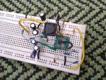
But please give the part number of yourt inductor, and a photo of your circuit.

IMG_20191004_164926.jpg

this is the circuit, I think it answers all your questions.

I have ordered the inductor through Aliexpress so i do not its part number.

If you can spot the mistake it would be very helpful

thanks in advance.
 

sure I will try this and tell.

currently i do not have 7.5uh value I will check with this after buying.


View attachment 155868

this is the circuit, I think it answers all your questions.

I have ordered the inductor through Aliexpress so i do not its part number.

If you can spot the mistake it would be very helpful

thanks in advance.

I can spot the mistake: those protoboards are TERRIBLE for the type of circuit you are playing with. Stray inductance, stray capacitance, etc. Usually, the manufacturer shows a recommended PCB layout; it would look nothing like what you've got there.

I would STILL verify that the output of that "20-70Volt lead acid battery you spoke of" is not dropping.
 
yes....and your fsw is 400khz and you are doing it on breadboard......im sorry but i dont think its worth your while to continue unless you do it on a pcb, and use here my pcb layout doc

- - - Updated - - -

Please stop...please stop doing it on breadboard...i am afraid you are wasting your time...please stop
 

Attachments

  • Basics of SMPS Layout _4.doc
    645.5 KB · Views: 136
You specified Vin = 20-60V in post #1. What's the actual battery voltage?
I have 4 batteries each 12V connected in series to get 48V.

It's however easy to check if Vin drops or stays stable under load, isn't it?
Yeah, i checked Vin but it stays stable under load.
 

Hi,

Please stop...please stop doing it on breadboard...i am afraid you are wasting your time...please stop
I have to agree with this.
A breadboard simply is not suitable for this application.
It can't fulfill the design requirements.

Klaus
 

Please stop...please stop doing it on breadboard...i am afraid you are wasting your time...please stop

Oh,I agree
I have been wasted my time by working with breaboard. If breaboard is not suitable for this type of application means then how can we straight away go to PCB before checking its working conditions with suitable component values.
isn't there any alternative for breadboard except PCB? because I want to check with different component values.
And one more qsn. is what big companies are using?

- - - Updated - - -

I can spot the mistake: those protoboards are TERRIBLE for the type of circuit you are playing with. Stray inductance, stray capacitance, etc. Usually, the manufacturer shows a recommended PCB layout; it would look nothing like what you've got there.

I would STILL verify that the output of that "20-70Volt lead acid battery you spoke of" is not dropping.

1. I agree that protoboard is not suitable. I have also checked with PCB board the voltage is dropping like same as in breadboard.

2. I have verified the lead acid battery voltage which is not droping. and I am comparing my circuit with the original tps module which is working properly with same supply.
 

Hi

If breaboard is not suitable for this type of application means then how can we straight away go to PCB before checking its working conditions with suitable component values.
I´m designing circuits for many years now. I´m doing amost no simulation and no test circuit.
I´m reading the datasheet, especially the design notes, then directly go to the end-design.

My idea behind this: "If you keep on the datasheet - the circuit will work".

Other designers do it in a different way. There is no "one and only" best way.
--> You need to find your own way.

isn't there any alternative for breadboard except PCB?
Many IC manufacturers provide evaluation boards, or at least a PCB design example in the datasheet.


I have also checked with PCB board the voltage is dropping like same as in breadboard.
Show your exact schematic PCB layout and BOM with exact type of the used parts, especially C and L.
My opinion: There is no other reliable way than PCB - for those design critical applications.

Klaus
 

"isn't there any alternative for breadboard except PCB? because I want to check with different component values.
And one more qsn. is what big companies are using?"

-> These converters layout very much important, Strictly BIG NO to Breadboard.
1st option purchase an EVB
2nd option use double sided general purpose/**broken link removed** and design the circuit carefully.
This needs expertise/supervision - do as per page 39 layout guidelines
Inductor,diode,FB, RT/CLK, Input capacitor connections are critical

In your schematic you have not mentioned the part numbers of components.
Mention inductor,diode part numbers, Input,Output & Boot capacitor part numbers/atleast voltage ratings type of capacitor etc.

If you can spend time for debugging, we need captures of Switch node, feedback node, Output voltage for help.

Check IC, Inductor,Diode for any heat using your finger during operation.

last one is TPS54560 is old and Not recommended - tested with suggested chip from TI.
 

Status
Not open for further replies.

Similar threads

Part and Inventory Search

Welcome to EDABoard.com

Sponsor

Back
Top