Continue to Site

Welcome to EDAboard.com

Welcome to our site! EDAboard.com is an international Electronics Discussion Forum focused on EDA software, circuits, schematics, books, theory, papers, asic, pld, 8051, DSP, Network, RF, Analog Design, PCB, Service Manuals... and a whole lot more! To participate you need to register. Registration is free. Click here to register now.

1VAC to 1VDC converter using OPAMP

Status
Not open for further replies.

uj1964

Newbie level 6
Newbie level 6
Joined
Mar 12, 2018
Messages
14
Helped
0
Reputation
0
Reaction score
1
Trophy points
1
Activity points
121
Need help in making 1VAC to 1VDC converter. I tried to simulate on PROTEUS different OP-AMP circuits available on net. But not working. it always give high voltage(supply voltage) at output when input is given 1VAC.

May pls. help.
 

Sounds like you forgot to add the negative feedback.

I suspect you really want a unity-gain precision rectifier circuit. An op-amp circuit alone will not convert AC to DC.

Brian.
 
I presume you are asking about precision rectifier. Come back with the schematic that doesn't work for you.
 

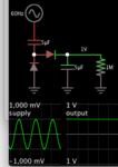
This method is not precisely the same as the thread topic but it has the same result. And it needs no op amp.
Villard voltage doubler. Accepts AC sine 1V amplitude, converts to 1VDC output.

The only reason it works at 1V amplitude, is because the diode drops are the same amount as the charge pump additive amount. So it wouldn't work the same at greater supply amplitude.

Villard doubler 2 diodes 2 caps AC sine 1V amplitude to 1V DC output.png

I cheated a little by adjusting diode V a tiny bit, to 0.758V 1A.
 
  • Like
Reactions: uj1964

    uj1964

    Points: 2
    Helpful Answer Positive Rating
Hi,

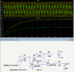
I have never made this circuit in the real world, so caveat emptor. This is only a simulation - that I trust, at least, and will need a) checking with real components, and b) tweaking on your part to make it less rough and ready. i.e. Look at the unpleasant ripple, if you're looking for ultra-smooth "perfect" DC. I'd guess that the choice of op amp influences the real world results, too.

I copied the precision rectifier circuit on page 5 from this website's pdf called Precision Rectifier Circuits

1VAC to 1VDC schematic and transient results.JPG

Hope it helps.
 
  • Like
Reactions: uj1964

    uj1964

    Points: 2
    Helpful Answer Positive Rating
Hi,

You know, that 1V AC is no complete information.
What waveform are you talking about, and is "1V"
* amplitude (peak)
* RMS
* rectified average
* or anything else.

Klaus
 

Your implementation is different from links page 5 in two regards.
- due to lack of a negative supply, the rectifier output for positive input isn't exactly clamped to zero
- the modified filter stage is more acting like a peak detector than the original averaging circuit

Wanting minimal output ripple, you'll usually prefer a full wave rectifier circuit. There's a single OP, single supply full wave rectifier circuit, unfortunately not listed in the link. Gain is below unit, but can be enhanced in the succeeding filter stage.
 
  • Like
Reactions: d123

    d123

    Points: 2
    Helpful Answer Positive Rating
Hi,

Your implementation is different from links page 5 in two regards.
- due to lack of a negative supply, the rectifier output for positive input isn't exactly clamped to zero
- the modified filter stage is more acting like a peak detector than the original averaging circuit

- That's referrring to the -19mV I saw in the simulation results?
- Okay, thanks.

Also, R1 and R2 function as a resistor gain section, do they?

There's a single OP, single supply full wave rectifier circuit, unfortunately not listed in the link. Gain is below unit, but can be enhanced in the succeeding filter stage.

Could you possibly post a link to that circuit or a schematic, please? I've had a little little search for "full-wave rectifier op amp" and "single OP, single supply full wave rectifier circuit" but so far they all come up as two OA versions. Just curious/interested to see it. Thanks.

- - - Updated - - -

Is it this circuit that you mean?

LMC6482 datasheet fullwave rectifier schematic.JPG
 
  • Like
Reactions: FvM

    FvM

    Points: 2
    Helpful Answer Positive Rating
Indeed, a precision full wave rectifier requires two opamp blocks,
but because dual 8-pin opamp packages are ubiquitous, this translates as a single IC package.
 
Is it this circuit that you mean?
Yes. As the example shows, it can be also implemented with unity gain if the load resistance is infinite.
 
  • Like
Reactions: d123

    d123

    Points: 2
    Helpful Answer Positive Rating
Here's a variation of the one-diode full-wave precision rectifier with second-stage gain.
The RC filter gives the average value of the full-wave rectified output.
The gain value for U4 shown, gives an equivalent DC output equal to the RMS of the input sinewave (.707/.636 of the average).
The gain can be changed to give the equivalent peak value if desired (gain = 1.572).

Capture.PNG
 
  • Like
Reactions: uj1964 and d123

    d123

    Points: 2
    Helpful Answer Positive Rating

    uj1964

    Points: 2
    Helpful Answer Positive Rating
Hi,
I am not expert in design. I just surf net and tried to simulate this circuit on protius.
Pls. see attachment.

Will try other circuit as you advised.
 

Attachments

  • 1VAC_1VDC.jpg
    1VAC_1VDC.jpg
    302.7 KB · Views: 243

Hi,

you asked about "1VAC to 1VDC converter" ...
But the output of your circuit surely is not DC, It is the rectified input wave.

DC is ia straight horizontal line on the scope.

Now my question is:
Do you just want the rectified signal at the output, or do you want DC at the ouput?

Klaus

BTW: In any case I recommend to use an unity gain buffer at the ouput, because the node is relatively high ohmic.
And don´t use outdated 741 Opamp, better use a much better modern one.
 
  • Like
Reactions: uj1964

    uj1964

    Points: 2
    Helpful Answer Positive Rating
It should not vary. It is only 1V

I need DC at the output. I will try to use another OPAmp.
Thanks.
 

Hi,

If you want DC at the output, then you need the already recommended buffer and (I recommend a second order) low pass filter.
Because you don't give any specifications about input frequency and output ripple..I can'tgive any value recommendations.

The filter calculates "rectified average". For a sine waveform this is: sine_amplitude × 2 / Pi.
If you want to get 1V output, then you simply could compensate this by setting the correct gain at the buffer (instead of unity gain)

Klaus
 

I need DC at the output.
Any rectifier circuit has some residual ripple. You can reduce it by increasing the filter time constant at the expense of high settling time.
 

Status
Not open for further replies.

Similar threads

Part and Inventory Search

Welcome to EDABoard.com

Sponsor

Back
Top