Continue to Site

Welcome to EDAboard.com

Welcome to our site! EDAboard.com is an international Electronics Discussion Forum focused on EDA software, circuits, schematics, books, theory, papers, asic, pld, 8051, DSP, Network, RF, Analog Design, PCB, Service Manuals... and a whole lot more! To participate you need to register. Registration is free. Click here to register now.

Paralel connection of multiple LLC converters with synchronous rectification.

Status
Not open for further replies.

rxpu

Member level 3
Member level 3
Joined
Mar 9, 2019
Messages
58
Helped
0
Reputation
0
Reaction score
1
Trophy points
8
Activity points
819
I am trying to paralel 6 LLC converters each having their own synchronous rectification.

Each converter has its own frequency control, so each have different phase and amplitude with respect to each other.

Each converter has its own closed loop voltage and current control. So a runaway of a single converter in the group is unlikely.

But I have some uncertainity:

If I have simple diode rectification a reverse current flow is not possible. But what if I use mosfet based synchron rectification and when the mosfets conduct will it allow backward current flow?

My concern: When any of the rectifier mosfets are conducting at the same time and if the phase and amplitdues are different (as they have different controllers) , can an excessive current flow between the secondary windings of the power supplies?

Any ideas?
 

Depends on how "voltage and current control" is implemented. If the converter involves voltage ratio variation (e.g. by frequency control) and an I controller, some kind of load balancing may be necessary. Unbalanced load can also happen without bidirectional operation (synchronous rectification), just no energy circulation.
 

Depends on how "voltage and current control" is implemented. If the converter involves voltage ratio variation (e.g. by frequency control) and an I controller, some kind of load balancing may be necessary. Unbalanced load can also happen without bidirectional operation (synchronous rectification), just no energy circulation.

You mean that there must be an outer Voltage loop (slower) and an inner current loop (faster) . Each controller must report its current current value to the host to be sure that the current is balanced.

Example: Host controller initiates a voltage Mode control setting an output voltage of ex 5.6V

Each controller starts regulating and reach a certain current step ex:

first converter: 5.8V 80A
second controller : 5.7V 60A
Third controller : 5.4V 20A
Fourth controller : 5.9V 120A
Fifth converter: 5.3V 10A
Sixt converter : 5.2V 5A

The host controller adds the currents and finds Itotal= 80A+60A+20A+120A+10A+5A= 395A

Host calculates the ideal shared balance= 395A/6=65.83A

Each converter receives that the balanced current is 65.83A and tries to regulate the current by adjusting their frequency (and consequently the output voltage)


After some iteration the voltages will get closer and the currents will also get balanced resulting slightly different frequencies because of the minor differences of the resonant parameters of each converter.

Is this way of thinking the right way to solve the problem? Or should I investigate something else?
 

It's ideal if each converter is run in current mode control with its own fast current loop. Then the top level controller simply runs an outer voltage loop, commanding each converter to 1/6th of its desired current.


In general the type of 'balancing' loop you describe should be possible but consider eliminating the individual voltage loops. Start by envisioning that each converter is running at the same base frequency. A balancing loop senses the individual currents and modifies the individual frequencies to balance them.

Then run an outer voltage loop that modulates the base frequency to get the final output.


Do you your best to find papers on this subject. I bet you'll find some content on paralleling LLC converters.

Thank you for the detailed info.

What I understand:

Assuming Voltage control mode,Vout=5.6V

Each converter runs a fast current loop. Start slowly by increasing the current . The converter also has a slower outer voltage loop.
If the Voltage limit is reached (V=5.6V) the current loop stops increasing the current. the faster internal current loop adjusts itself to hold the Voltage at 5.6V

If the host commands a new Voltage set point, the current loop reacts by increasing or decreasing the current (by increasing/decreasing the frequency) to reach the new Voltage setpoint.


The only uncertainity: Each seperate converter has its synchronous Mosfet rectifier at its output. Each converter has random phase and voltage amplitude.

If all secondary windings with different phase and amplitude conditions are connected togethar can it be that the one mosfet of a converter is shorted with another.

Or maybe because of a minimal voltage difference , one converter has no current flow and sees its ouput as open load. How can we avoid this situation.
 
Last edited:

The only uncertainity: Each seperate converter has its synchronous Mosfet rectifier at its output. Each converter has random phase and voltage amplitude.

If all secondary windings with different phase and amplitude conditions are connected togethar can it be that the one mosfet of a converter is shorted with another.
I presume the converters will be paralleled with the DC outputs. The AC phase doesn't matter then.

I agree with your sketch of a balancing controller but also with the comment that the structure may be simplified by using a single voltage controller. In this case, the current imbalance may be small enough to get away without explicit balancing.
 
  • Like
Reactions: rxpu

    rxpu

    Points: 2
    Helpful Answer Positive Rating
If the converters can be configured master/slave and you
have current mode control then load balancing may just
happen. We designed POls with sync rect FETs on chip
so that they would operate 2-phase and I saw few-%
current match at low, sub-% match at high current (to
10A per phase).

But -can- you configure them master/slave? If you let
them independently figure their own feedback then it
may result in lost efficiency with sync rect because of
the reverse current flow you mention.

Polyphase would be better for how hard you slug the
input source. Not clear in the lead post whether those
different voltages are a conjecture or a goal.
 
  • Like
Reactions: rxpu

    rxpu

    Points: 2
    Helpful Answer Positive Rating
Generally the best method is to have accurate volt and current settings on each rectifier - command them all to be the same - then work out the system average current and command the lower ones up by 5mV steps ( slowly ) and the higher ones down in 5mV steps ( slowly ) until the currents are balanced to within +/- 5A ...

For synch rect, each psu must avoid reverse current flow by its own control ( usually by lowering the freq on LLC )

I have used this approach successfully on very large telecom systems 48V 50A rectifiers x 30
 

    FvM

    Points: 2
    Helpful Answer Positive Rating

    rxpu

    Points: 2
    Helpful Answer Positive Rating

    Velkarn

    Points: 2
    Helpful Answer Positive Rating
I presume the converters will be paralleled with the DC outputs. The AC phase doesn't matter then.

I agree with your sketch of a balancing controller but also with the comment that the structure may be simplified by using a single voltage controller. In this case, the current imbalance may be small enough to get away without explicit balancing.

What I exactly mean: Diode is unidirectional, but mosfet is not. Mosfet is bidirectional when switched on.

Assuming a capacitor is at the output of the sync.rectifier and this cap is charged ex: 6V

The mosfet is switched on after the secondary winding voltage rises above 25mV.

This means there is a sequence where the cap bus voltage is 6V and the secondary rises from 25mV to 6V. During this transition where the secondary is less than 6V, can it be that the cap supplies current into the secondary winding rather than the secondary winding charges the cap just because the mosfet is a bidirectional switch. (it would not happen if there were a diode instead of mosfet)

This is also a general question for a synchronous rectifier regarding the bidirectional behaviour of the mosfet switch. How is this interaction minimized between the secondary winding and the capacitor current flow because of the bidirectional nature of the mosfet switch?

During the transition time when the secondary is rising from 25mV to 6V, when mosfet is on, the output cap seesr the secondary winding as a lower impedance path and supplies a reverse current through the secondary winding?

- - - Updated - - -

If the converters can be configured master/slave and you
have current mode control then load balancing may just
happen. We designed POls with sync rect FETs on chip
so that they would operate 2-phase and I saw few-%
current match at low, sub-% match at high current (to
10A per phase).

But -can- you configure them master/slave? If you let
them independently figure their own feedback then it
may result in lost efficiency with sync rect because of
the reverse current flow you mention.

Polyphase would be better for how hard you slug the
input source. Not clear in the lead post whether those
different voltages are a conjecture or a goal.

The converters have a master and master sends the operating point over a comm.bus. But it is only a communication channel. Each converter has its own control and they are not synchronised. In fact even if I try to synchronise the frequencies of the converters, it will not function because each converter has its own resonant tank. This means each have their own seperate and slightly different resonant freq.

Do you believe that phase synchronisation of each converter helps. In this case I will need more precise matching of the resonant components. It is also not easy to sync a variable freq of 100-200kHZ between seperate converters which are also physically apart from each other. Each converter is a thick copper PCB with integrated magnetics stacked 10cm apart from each other.

- - - Updated - - -

Generally the best method is to have accurate volt and current settings on each rectifier - command them all to be the same - then work out the system average current and command the lower ones up by 5mV steps ( slowly ) and the higher ones down in 5mV steps ( slowly ) until the currents are balanced to within +/- 5A ...

For synch rect, each psu must avoid reverse current flow by its own control ( usually by lowering the freq on LLC )

I have used this approach successfully on very large telecom systems 48V 50A rectifiers x 30

Have you synchronised the phase of each converter?.Did you use PSFB or LLC variable freq.

My configuration is 3.6V-6.8V output @300A x 6 paralel converters (sum 1800A)
 

No, you don't need to synch the converters - we used an LLC variant - parallel btw, 300A is a lot for LLC - the ripple current in the o/p caps for each stage will be ~ 120A - so you will need impressive caps to handle the ripple - the heat in the caps will be ESR x 120^2 so 1 milli-ohm gives 14.4 watts - but I guess you have already considered this. For high current it is more usual to employ a current doubler ( FBPS on the pri ... ) also you can get automatic current sharing between modules using current mode control ( peak or ave ) on each primary side ...
 
  • Like
Reactions: rxpu and FvM

    FvM

    Points: 2
    Helpful Answer Positive Rating

    rxpu

    Points: 2
    Helpful Answer Positive Rating
No, you don't need to synch the converters - we used an LLC variant - parallel btw, 300A is a lot for LLC - the ripple current in the o/p caps for each stage will be ~ 120A - so you will need impressive caps to handle the ripple - the heat in the caps will be ESR x 120^2 so 1 milli-ohm gives 14.4 watts - but I guess you have already considered this. For high current it is more usual to employ a current doubler ( FBPS on the pri ... ) also you can get automatic current sharing between modules using current mode control ( peak or ave ) on each primary side ...


In fact the load does not require a completely smooth DC signal. It may work also without a smoothening capacitor. So I do not plan to use capacitors or I use maybe some arrengement using very small capacitors so that the ripple current on the caps is much less maybe 20A. Without using inductors it is also a challege to reduce the ripple current of the caps by using smaller uF values.


Another interesting approach is, what if I do not rectify the secondary. I have a sine wave at the output. Instead of center tapped I may use current doubler output. One end is the reference GND and the other is a sine wave. the center of the sine wave is not GND but at GND+V(t)/2. I am sure the load is tolerant to sine wave.

But unfortunatelly ,in this arrangement , connecting the Ac secondary outputs of the converters each having different phase and frequency is a problem. they will short each other in random , dependant on the phase and frequency of each other.

If I could synchronise the phase and frequency of each converter maybe it would be possible to connect the AC sides togethar.

Any ideas?

- - - Updated - - -

For synch rect, each psu must avoid reverse current flow by its own control ( usually by lowering the freq on LLC )

I have used this approach successfully on very large telecom systems 48V 50A rectifiers x 30

How can you avoid the reverse current by lowering the freq on LLC, would you please give some details.

Do you mean going below resonance by lowering the frequency or soething else?. How will this avoid reverse current flow?

Is reverse current flow more problematic for LLC ,because the rise time of the sinus signal is much slower and reaching the peak needs exactly T/2 (half of the period) and in a sudden it goes down again. The shape of the voltage is very different than PSFB where we have a square wave signal which reduces the risk of reverse current.
 

Your last considerations about paralleling the AC output is clearly beyond the thread topic "LLC converters with synchronous rectification" but the answer is simple. Yes you need phase locked LLC drivers respectively a common signal generator.

Synchronization may be also useful with parallel connected DC outputs,, to get deterministic EMI behavior and possibly reduce in- and output ripple by phase shifting.
 
  • Like
Reactions: rxpu

    rxpu

    Points: 2
    Helpful Answer Positive Rating
Your last considerations about paralleling the AC output is clearly beyond the thread topic "LLC converters with synchronous rectification" but the answer is simple. Yes you need phase locked LLC drivers respectively a common signal generator.

Synchronization may be also useful with parallel connected DC outputs,, to get deterministic EMI behavior and possibly reduce in- and output ripple by phase shifting.

In deed, I added the option paraleling the secondary AC output to compare it to the sync.rectification.

In switched state we can model the mosfet as a very small resistor.

So if we have different random sources with different phase and freq. the paralel connection of these sources even with sync. rectification behaves like a paralel connection of pure unsynchronized AC sources. Am I right?

I know ,I miss something. But why is a bundle of different pure AC outputs different than a bundle of mosfet switched unsynchronised outputs?

- - - Updated - - -

If the converters can be configured master/slave and you
have current mode control then load balancing may just
happen. We designed POls with sync rect FETs on chip
so that they would operate 2-phase and I saw few-%
current match at low, sub-% match at high current (to
10A per phase).

But -can- you configure them master/slave? If you let
them independently figure their own feedback then it
may result in lost efficiency with sync rect because of
the reverse current flow you mention.

Polyphase would be better for how hard you slug the
input source. Not clear in the lead post whether those
different voltages are a conjecture or a goal.


I exagerate the voltages to show that for an unsynchronized arrangement the regulation of the voltage may be problematic.
I am trying to decide if I synchronize the phase and freq of all slaves to a reference clock so that voltage control is less complex. Efficiency may be also better because the different levels of the multiple converters may cancel some of the current flow of some converters which have lower voltage state at this time sequence.
 
Last edited:

The thread has covered lots of different options for paralleling. Personally I think for someone with limited experience the safest bet is to design one current mode controlled converter (peak or average as Easy Peasy also mentioned).

This is a discrete design where you'll have references to draw upon and when you go to parallel it it will 'just work'. In case you're not familiar 'current mode control' doesn't just mean it has a current loop somewhere, it (typically) means current is regulated at a low level in a high bandwidth way. Current mode control has several benefits with easy paralleling being one of them.
 
  • Like
Reactions: rxpu

    rxpu

    Points: 2
    Helpful Answer Positive Rating
I am assuming you have never done any thing similar before? to completed and working?

you could, in theory, parallel the AC output of the LLC transformers - ideally you would put an extra choke in the output for part passive current sharing.

However you would need to do the following:

* All the L's and C and Tx's for the LLC converter would need to be identical, better than 0.5%

* the gate drive would need to be copied to all converters - exactly.

* the source feeding the converters would need to be the same, i.e. if a single source the same DC resistance to all converters

* the output wiring would need to be identical, i.e. same DC resistance to a common point.

- - - Updated - - -

Please note that for bad parts mismatches - you have no protection against reverse current flow ( all gate drives the same ) and could get power going out of one converter and back to the source via another ...

for a rectified output your query:
How can you avoid the reverse current by lowering the freq on LLC, would you please give some details.

lowering the freq raises the Vout which reverses a reverse current flow ( individual control on each converter ) - also at light loads you can turn the rect fets off and just have diode rectification ...
 
  • Like
Reactions: rxpu

    rxpu

    Points: 2
    Helpful Answer Positive Rating
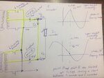
I thank all of you for the detailed information. I send a sketch showing my concern that secondary windings shorting between multiple converters working at different frequencies and phases.

According to the following sketch, I see that there is a huge current flow between Point A and Point B when the converters have different frequencies and phases. In this case Point A is forced to rise to 10Vpeak and point B which is also shorted with point B is forced to 1V which will result in a huge current flow between the seconaries.

According to this it is impossible to connect the multiple converters that has different freq. and phase?.Is it true?


LLC-secondaryParalel-Conducting.jpg
 

Well you left off the output cap. Consider that the output cap is a voltage source which in some sense is always 'shorting' the output of your converter - it's shorting it to the voltage stored in the cap.

The real question is whether the two converters 'want' significantly different voltages. If yes then current will circulate between them. If no then all is good.

In general you're overthinking things a bit. Yes circulating current between multiple output phases is an issue but people have given lots of examples of why it might be ok and/or how to directly address it.
 
  • Like
Reactions: rxpu

    rxpu

    Points: 2
    Helpful Answer Positive Rating
Well you left off the output cap. Consider that the output cap is a voltage source which in some sense is always 'shorting' the output of your converter - it's shorting it to the voltage stored in the cap.

The real question is whether the two converters 'want' significantly different voltages. If yes then current will circulate between them. If no then all is good.

In general you're overthinking things a bit. Yes circulating current between multiple output phases is an issue but people have given lots of examples of why it might be ok and/or how to directly address it.

Can we say that the capacitor is a voltage source and shorting the output while the secondary winding and its inductor is acting as a current source . The inductor as a current source should have then a high impedance.

It should mean that when one converters sync. mosfet is on and the switched voltage reaches 10V, and the other converters synch mosfet switched and the voltage reaches 2V.
They will source the current to cap but not between each other (between point A (10V) and point B (2V)) because the secondaries and their windings as inductors act as current source and have high impedance?
Can we say that?
 

Status
Not open for further replies.

Similar threads

Part and Inventory Search

Welcome to EDABoard.com

Sponsor

Back
Top