Continue to Site

Welcome to EDAboard.com

Welcome to our site! EDAboard.com is an international Electronics Discussion Forum focused on EDA software, circuits, schematics, books, theory, papers, asic, pld, 8051, DSP, Network, RF, Analog Design, PCB, Service Manuals... and a whole lot more! To participate you need to register. Registration is free. Click here to register now.

efficient led driver circuit?

Status
Not open for further replies.
J

Javid.zare.s

Guest
Newbie level 1
hi, since my powerbank didn't come with leds im planning to add 6 leds on it but the problem is that using them with resistors generates a lot of heat and I feel uncomfortable about this, so im thinking about using ne555 to perform high frequency& efficient driving. I couldn't find any circuit design that works for 6 leds ,so I'll be happy if you help me out.
power source 5v2a, I have 555 timeric and bunch of common transistors and resistors tnx
 

Hi,

How much heat do you expect?
10mA per LED should be sufficient. With about 2V at the LED, then the remaining voltage at the resistor is about 3V.
This generates about 30mW of heat ... you barely can feel this.

Klaus
 

    V

    Points: 2
    Helpful Answer Positive Rating
Hi,

How much heat do you expect?
10mA per LED should be sufficient. With about 2V at the LED, then the remaining voltage at the resistor is about 3V.
This generates about 30mW of heat ... you barely can feel this.

Klaus

thanks for the reply, I don't know much about electrics, there are 6 leds and honestly I don't know how to put them together, In parallel or series? I configured into 3 groups of parallel and in each 2leds in series , one 10 ohm resistor at the end, is this ok?
 

why 6 leds?
are you using them as indicators for something?
you have 5V output, one led to indicate 5V is on/off needs one resistor and one led
2V across the led, 3V across the resistor, at 10 mA means you need a 300 ohm resistor
300 ohm is a standard value.
if you're building is by hand, get a 1/4 watt so its easy to handle.
 

    V

    Points: 2
    Helpful Answer Positive Rating
With a 555 you could build a current regulated boost converter. Fairly simple as custom power design goes but it is custom power design. Off-the-shelf LED controllers can be found that are designed for exactly with with an application circuit you can copy.

Note that Linear LED driving can be fairly efficient if you can minimize the linear drop by putting the right number of LED's in series. For example if your LED's really are 2V with 5V you can drive 2 in series dropping 1V across a linear current source. That's 80% efficient with no switching needed.
 

    V

    Points: 2
    Helpful Answer Positive Rating
Hi,

thanks for the reply, I don't know much about electrics, there are 6 leds and honestly I don't know how to put them together, In parallel or series? I configured into 3 groups of parallel and in each 2leds in series , one 10 ohm resistor at the end, is this ok?

Whether this is OK or not depends on the type of LEDs. In detail: the expected LED current and the LED forward voltage.
We can't know what LEDs you use. Thus it's impossible to validate

Klaus
 

    V

    Points: 2
    Helpful Answer Positive Rating
why 6 leds?
are you using them as indicators for something?
you have 5V output, one led to indicate 5V is on/off needs one resistor and one led
2V across the led, 3V across the resistor, at 10 mA means you need a 300 ohm resistor
300 ohm is a standard value.
if you're building is by hand, get a 1/4 watt so its easy to handle.
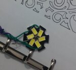
oh not for indication or anything else, I wanna use it as flash light, here's how they look, voltage across each led is 2.5 volts
IMG_20190407_133451_edit.jpg
my arrangement is calculated by this website :
IMG_20190405_123449.png

With a 555 you could build a current regulated boost converter. Fairly simple as custom power design goes but it is custom power design. Off-the-shelf LED controllers can be found that are designed for exactly with with an application circuit you can copy.

Note that Linear LED driving can be fairly efficient if you can minimize the linear drop by putting the right number of LED's in series. For example if your LED's really are 2V with 5V you can drive 2 in series dropping 1V across a linear current source. That's 80% efficient with no switching needed.

my leds are smd type and I think 2v is enough for each one, and they are in series like you said but is it ok to drop the voltage by a diode? they drop voltage for about 0.7v, is it a good way? what about resistor for current limiting?


Hi,


Whether this is OK or not depends on the type of LEDs. In detail: the expected LED current and the LED forward voltage.
We can't know what LEDs you use. Thus it's impossible to validate

Klaus

ok, we have 6 smd leds with 2v and 20mA forward voltage and current, I wanna make a bright and durable flashlight out of this and I found this circuit, but it is designed for a single led, so what should I do? replace the self with a better one?
also which transistor is good for Q1? (any pnp or something else?)
ZZjs9.png
 
Last edited:

The calculation is simply R = (Battery voltage - (Vf of series LEDs added together)) / I
Where R is in Ohms, Vf is the forward voltage of each the LED, and I is in Amps.

So if the battery is 5V, the LED Vf is 2V and you want 10mA current with two LEDs in series: R = (5 - (2 x 2))/0.01 = 100 Ohms.

The power lost in the resistor is: W = (Battery voltage - (Vf of series LEDs added together)) * I
Where W is in Watts. So all you lose is (5 - (2 x 2)) * 0.01 = 0.01W which is hardly anything.

Adding two LEDs in series is fine but I would not advise you to wire them as three parallel circuits of two in series then a single resistor. Instead wire them as three parallel circuits of two, each with a series resistor. So you have three resistors in total. The reason is that there is some natural variation in the Vf of LEDs and if you wire them directly in parallel the current tends not to be equal down each path, you get some LEDs brighter than others and maybe overloaded in doing so. A resistor in each series pair prevents that happening.

Caution: Check the real voltage of your 'powerbank' before going any further. Sometimes the ones marked 5V are intended for recharging devices with internal 5V battery packs but they sometimes need more than 5V to be able to 'push' current into them. It is quite possible that your 'powerbank' produces more than 5V.

Brian.
 

Hi,

voltage across each led is 2.5 volts
my leds are smd type and I think 2v is enough for each one,
I doubt that a LED, which has nominal firward voltage if 2.5V will light with 2.0V only.
And LEDs need to be current driven.

Usual two LEDs with a 10 Ohms series resistor may widely vary brightnees.... depending onsupply voltage variation, and temperature.
Any tiny voltage change will result in big current change. Usually not the situation one wants...

--> you really need to keep on datsheet values. No "estimation".

Klaus
 

do you have a part number for the LEDs? or for the assembly, since it loos like they came pre-wired ? if you do, please provide it

are they wired according to the wiring diagram you provided?

if your power supply is 5V, and the LEDs are in fact 2.5V, there is no overhead for the resistor.

you will have to wire it as 6 parallel (led and resistor). in that case, 5 V - 2.5 V across the led leaves 2.5 V across the resistor
at 10 mA, 2.5 V /10 ma = 250 ohm
250 ohm is not a standard value so you should go with the 240 ohm

then 2.5 V / 240 ohm 10.4 mA and the power requirement is 2.5 V * 10.4 mA = 0.026 W per resistor.
so you want 240 ohm 5% 1/8 Watt resistors

to compensate for the variations in light output based on minor variations in current requires a data sheet
(for the necessary information) and a more complex circuit
 

The LED forward drop at 10mA for red leds is less than 2V; typically about 1.8V. Test with a multimeter; most digital multimeters test the forward drop of the diode junction at 10mA (check the manual).

The LED will glow with the full brightness. If the brightness is much less, probably the multimeter is using 1mA test current.

If the LED is blue (color), then the forward drop will be much higher: around 3.1-3.3V - if your supply is 5V you cannot use two in series because you will get very little light.

For green or yellow, the values will be different.
 

    V

    Points: 2
    Helpful Answer Positive Rating
I wanna use it as flash light
...
View attachment 152272

The above schematic is from post #7. It's similar to a boost converter. It is able to output sufficient voltage to drive all six led's in series. A characteristic of an inductor is that it maintain current flow after shut-Off. Thus it generates sufficient voltage to (briefly) overcome the load's threshold voltage. (Even to the point where it creates high voltage spikes).

To make a flashlight we wish to make the led's the brightest light we can. However the above schematic sends brief current pulses to the the led's, flashing them for a short portion of the duty cycle. It yields reduced light intensity.

Here is a boost converter which has only an invert-gate switching it on and off. The led's stay lit continually due to the smoothing (reservoir) capacitor. All led's receive the same Ampere level. None are imbalanced. It's a benefit from hooking them up in series.

boost conv controlled by invert-gate 23kHz 5v to 13v led load.png

Adjust potentiometers so you obtain desired output. Frequent advice says the inverter gate should not be exposed to a higher voltage than its power supply.

------------------------------------

The 1nF capacitor doesn't look as though it's needed to contribute to proper operation. However it turned out to be a simple and easy way to avoid having the simulator lapse into stagnation. The capacitor and inductor create brief ringing, which triggers the inverter to change state more easily.
 

    V

    Points: 2
    Helpful Answer Positive Rating
How about a Joule thief? You can see a demo at https://www.youtube.com/watch?v=K53beWYdIpc&t=1140s

The good thing is that it is efficient and simple. I suggest a small capacitor from the base to the ground (it may reduce the frequency of osc but may provide better stability).

With 5V input, you can run 6 red LEDs in series.
 

    V

    Points: 2
    Helpful Answer Positive Rating
I am also a newbie, I really want to help you, but I don't fully understand your problem. I think you can want an application 555 to control 6 LEDs. I can give you a 555 charging circuit. You can remove the battery part. It is very good to connect 6 LED lights.
Circuit diagram address:
**broken link removed**
 

The 555 voltage stepup circuit blinks the LEDs to dim them. Cheap solar garden lights use a circuit like that. The "yellow" LEDs are white ones with a forward voltage of from 3V to 3.6V. The SMD LED chips might not have matched voltages then will not work in parallel. 3.6V x 6= 21.6V which might not be available from the 555 circuit if the LEDs are in series.
 

The "yellow" LEDs are white ones with a forward voltage of from 3V to 3.6V...

Can you please elaborate a bit more?
 

Can you please elaborate a bit more?
A white LED is a blue one with a yellow phosphor on top. It barely makes any light with only 3V.
 

Attachments

  • white LED voltage.png
    white LED voltage.png
    76.4 KB · Views: 239
  • Like
Reactions: Kajunbee

    Kajunbee

    Points: 2
    Helpful Answer Positive Rating
    V

    Points: 2
    Helpful Answer Positive Rating
Status
Not open for further replies.

Part and Inventory Search

Welcome to EDABoard.com

Sponsor

Back
Top