Continue to Site

Welcome to EDAboard.com

Welcome to our site! EDAboard.com is an international Electronics Discussion Forum focused on EDA software, circuits, schematics, books, theory, papers, asic, pld, 8051, DSP, Network, RF, Analog Design, PCB, Service Manuals... and a whole lot more! To participate you need to register. Registration is free. Click here to register now.

Parking lot occupancy counter State Diagram

Status
Not open for further replies.

eengr

Member level 4
Member level 4
Joined
Mar 9, 2016
Messages
75
Helped
0
Reputation
0
Reaction score
0
Trophy points
1,286
Activity points
4,270
Hi I am working on this problem using VHDL design

It requires two inputs as two sensors (A & B) (as shown in the pdf attached)

View attachment Parking lot occupancy Counter.pdf

It has two outputs as ENTER_CAR & EXIT_CAR. They need to be asserted for ONE clock cycle depending upon if car is entering or leaving.

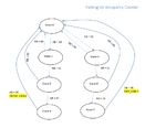
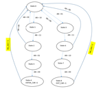
I have done the state diagram for this (as shown in the pdf attached)
State-diagram.png

Where I am struggling is the YELLOW HIGHLIGHTED 'ms_tick = 1' condition that takes the State-4 or State-8 back to State-0

I can generate this tick by using a counter but that will cause the OUTPUTS ENTER_CAR & EXIT_CAR to stay asserted for more than one clock cycle.

Is there a VHDL synthesizeable statement that I could use to check for 1 clock cycle and could be used to get out of these states?
 

Attachments

  • State-diagram.png
    State-diagram.png
    105.3 KB · Views: 447

Why not just create the tick on detecting the change of states?
 
  • Like
Reactions: eengr

    eengr

    Points: 2
    Helpful Answer Positive Rating
I have done the following mod:

State-diagram-mod-1.png

Where I now generate the output ticks when changing the state from State-3 to State-0 OR State-7 to State-0.

But problem I have is that depending upon when the state changes

IF the state changes on falling edge of my clock then, I get the output tick for HALF a Clock only

If the state changes on rising edge of my clock then, I get the output tick for FULL clock cycle.

Is there a way to get around this so that I get output tick for full clock cylce?
 

Yes only use the rising edge. You cannot use two edges in an FPGA anyway
 
  • Like
Reactions: eengr

    eengr

    Points: 2
    Helpful Answer Positive Rating
Ok I think I am still confused here.

Here is my code:


Code VHDL - [expand]
1
2
3
4
5
6
7
8
9
10
11
12
13
14
15
16
17
18
19
20
21
22
23
24
25
26
27
28
29
30
31
32
33
34
35
36
37
38
39
40
41
42
43
44
45
46
47
48
49
50
51
52
53
54
55
56
57
58
59
60
61
62
63
64
65
66
67
68
69
70
71
72
73
74
75
76
77
78
79
80
81
82
83
84
85
86
87
88
89
90
91
92
93
94
95
96
97
98
99
100
101
102
103
104
105
106
107
108
109
110
111
112
113
114
115
116
117
118
119
120
121
122
123
124
125
126
127
128
129
130
131
132
133
134
135
136
137
138
139
140
141
142
143
144
145
146
147
148
149
150
151
152
library IEEE;
use IEEE.STD_LOGIC_1164.ALL;
 
-- Uncomment the following library declaration if using
-- arithmetic functions with Signed or Unsigned values
use IEEE.NUMERIC_STD.ALL;
 
-- Uncomment the following library declaration if instantiating
-- any Xilinx primitives in this code.
--library UNISIM;
--use UNISIM.VComponents.all;
 
entity parking_lot is
    generic(N : integer := 3); --2^N * 20ns = 10ms - change it to 19
    Port ( clk, reset : in  STD_LOGIC; 
              a_frnt : in  STD_LOGIC;
           b_bck : in  STD_LOGIC;
              count_out : out STD_LOGIC_VECTOR(N-1 downto 0);
              tick_out : out STD_LOGIC;
           enter_car : out  STD_LOGIC;
           exit_car : out  STD_LOGIC);
end parking_lot;
 
architecture Behavioral of parking_lot is
    
    constant DVSR : integer := 1; -- no of 20ns cycles to generate 10ms tick Change this to 500000
    signal q_reg, q_next : unsigned (N-1 downto 0) := (others => '0');
    signal ms_tick : std_logic := '0';
    
    type eg_state_type  is (state0, state1, state2, state3,
                                    state5, state6, state7);
    signal state_reg, state_next : eg_state_type;
 
begin
 
    count_out <= std_logic_vector (q_reg);
    tick_out <= ms_tick;
    
    -- *********************************************
    -- Counter to generate 10ms tick
    -- *********************************************
    process (clk, reset)
    begin
        if (reset = '1') then
            q_reg <= (others => '0');
        elsif (clk'event and clk = '1') then
            q_reg <= q_next;
        end if;
    end process;
    
    -- next state logic
    q_next <= 
                (others => '0') when q_reg = DVSR OR reset = '1' else
                q_reg + 1;
    -- 10 ms_tick   
    ms_tick <= '1' when q_reg = DVSR else '0';
    
    
    -- *********************************************
    -- Car Enter/ Exit FSM
    -- *********************************************
    process (clk, reset)
    begin
        if (reset = '1') then 
            state_reg <= state0;
        elsif (clk'event and clk = '1') then
            state_reg <= state_next;
        end if;
    end process;
    
    -- next state logic & Output logic
    
    process (state_reg, a_frnt, b_bck, ms_tick)
    begin
        state_next <= state_reg; -- default back to same state
        enter_car <= '0'; -- default is 0
        exit_car <= '0'; -- default is 0
        
        
        case state_reg is
            when state0 =>
                if (a_frnt = '1' AND b_bck = '0') then
                    state_next <= state1;
                elsif (a_frnt = '0' AND b_bck = '1') then
                    state_next <= state5;
                end if;
                
            when state1 =>
                if (a_frnt = '0' AND b_bck = '0') then
                    state_next <= state0;
                elsif (a_frnt = '1' AND b_bck = '1') then
                    state_next <= state2;
                end if;
                
            when state2 =>
                if (a_frnt = '0' AND b_bck = '0') then
                    state_next <= state0;
                elsif (a_frnt = '0' AND b_bck = '1') then
                    state_next <= state3;
                end if;
                
            when state3 =>
                if (a_frnt = '0' AND b_bck = '0') then
                    enter_car <= '1';
                    state_next <= state0;
                end if;
            
--          when state4 =>
--              enter_car <= '1';
--              if (ms_tick = '1') then
--                  state_next <= state0;
--              end if;
                
            when state5 =>
                if (a_frnt = '0' AND b_bck = '0') then
                    state_next <= state0;
                elsif (a_frnt = '1' AND b_bck = '1') then
                    state_next <= state6;
                end if;
                
            when state6 =>
                if (a_frnt = '0' AND b_bck = '0') then
                    state_next <= state0;
                elsif (a_frnt = '1' AND b_bck = '0') then
                    state_next <= state7;
                end if;
                
            when state7 =>
                if (a_frnt = '0' AND b_bck = '0') then
                    exit_car <= '1';
                    state_next <= state0;
                end if;
                
--          when state8 =>
--              exit_car <= '1';
--              if (ms_tick = '1') then
--                  state_next <= state0;
--              end if;


        end case;   


    end process;


end Behavioral;


My test bench code is:


Code VHDL - [expand]
1
2
3
4
5
6
7
8
9
10
11
12
13
14
15
16
17
18
19
20
21
22
23
24
25
26
27
28
29
30
31
32
33
34
35
36
37
38
39
40
41
42
43
44
45
46
47
48
49
50
51
52
53
54
55
56
57
58
59
60
61
62
63
64
65
66
67
68
69
70
71
72
73
74
75
76
77
78
79
80
81
82
83
84
85
86
87
88
89
90
91
92
93
94
95
96
97
98
99
100
101
102
103
104
105
106
107
108
109
110
111
112
113
114
115
116
117
118
119
120
121
122
123
124
125
126
127
128
129
130
131
132
133
134
135
136
137
138
139
LIBRARY ieee;
USE ieee.std_logic_1164.ALL;
 
-- Uncomment the following library declaration if using
-- arithmetic functions with Signed or Unsigned values
--USE ieee.numeric_std.ALL;
 
ENTITY tb1 IS
END tb1;
 
ARCHITECTURE behavior OF tb1 IS 
 
    -- Component Declaration for the Unit Under Test (UUT)
 
    COMPONENT parking_lot
    PORT(
         clk : IN  std_logic;
         reset : IN  std_logic;
         a_frnt : IN  std_logic;
         b_bck : IN  std_logic;
         count_out : OUT  std_logic_vector(2 downto 0);
         tick_out : OUT  std_logic;
         enter_car : OUT  std_logic;
         exit_car : OUT  std_logic
        );
    END COMPONENT;
    
 
   --Inputs
   signal clk : std_logic := '0';
   signal reset : std_logic := '0';
   signal a_frnt : std_logic := '0';
   signal b_bck : std_logic := '0';
 
    --Outputs
   signal count_out : std_logic_vector(2 downto 0);
   signal tick_out : std_logic;
   signal enter_car : std_logic;
   signal exit_car : std_logic;
 
   -- Clock period definitions
   constant T : time := 20 ns;
 
BEGIN
 
    -- Instantiate the Unit Under Test (UUT)
   uut: parking_lot PORT MAP (
          clk => clk,
          reset => reset,
          a_frnt => a_frnt,
          b_bck => b_bck,
          count_out => count_out,
          tick_out => tick_out,
          enter_car => enter_car,
          exit_car => exit_car
        );
 
   -- Clock process definitions
   clk_process :process
   begin
        clk <= '0';
        wait for T/2;
        clk <= '1';
        wait for T/2;
   end process;
    --*************
    -- reset 
    --************* 
 
    reset <= '1', '0' after T/2;
 
 
   -- Stimulus process
   stim_proc: process
   begin        
      wait until falling_edge(clk);
        --****************************
        -- No car
        --****************************
        
        a_frnt <= '0';
        b_bck <= '0';
        for i in 1 to 3 loop
            wait until falling_edge(clk);
        end loop;
        
        --**********************************************************
        -- car enters block a_frnt sensor
        --**********************************************************
        
        a_frnt <= '1';
        b_bck <= '0';
        for i in 1 to 3 loop
            wait until falling_edge(clk);
        end loop;
        
        --**********************************************************
        -- car enters block a_frnt sensor & b_bck sensor
        --**********************************************************
        
        a_frnt <= '1';
        b_bck <= '1';
        for i in 1 to 3 loop
            wait until falling_edge(clk);
        end loop;
        
        --**********************************************************
        -- car enters un-block a_frnt sensor & blocks b_bck sensor
        --**********************************************************
        
        a_frnt <= '0';
        b_bck <= '1';
        for i in 1 to 3 loop
            wait until falling_edge(clk);
        end loop;
        
        --**********************************************************
        -- car enters un-block a_frnt sensor & un-blocks b_bck sensor
        --**********************************************************
        wait for 10ns;
        a_frnt <= '0';
        b_bck <= '0';
        for i in 1 to 3 loop
            wait until falling_edge(clk);
        end loop;
        
        
        --******************************
      --terminate Simulation
      --******************************


        assert false
        report "NS Simulation Completed"
        severity failure; 
   end process;
 
END;


I did two simulations one with the test bench as above. Other with line-120 (wait for 10ns) commented out

My simulation results with line-120 (wait for 10ns) commented out are:

enter_car_half_clk.png

My simulation results with test bench same as above are:

enter_car_full_clk.png

As it can be seen that 'enter_car' is ON for 1/2 clock cycle for 1st picture
& full-clock cycle for 2nd picture

This is what I am confused about as in what I am doing wrong here (what do I need to do to get the enter_car asserted for FULL Clock cycle)
 

Its probably because enter_car is a combinatorial output, and in state 3, if a_front and b_front are '0', enter_car will be '1'.

It would probably make more sense if you registered all the outputs and created a single process state machine, rather than 2 process.
 
  • Like
Reactions: eengr

    eengr

    Points: 2
    Helpful Answer Positive Rating

    rivia02

    Points: 2
    Helpful Answer Positive Rating
change state only on rising edge of a clock
ms_tick is set to 1 or 0 depending on the state, and must last for 1 clock cycle

state diagram from your second post:
states 1, 2, 5 and 6 look like no-operation states. move one (say state 2) to between state 3 and state 0 to assert enter_car for 1 clock cycle
likewise, move one (say state 6) to between state 7 and state 0 to assert exit_car for 1 clock cycle

you may want to re-assign state designation numbers to maintain the one bit change
 
  • Like
Reactions: eengr

    eengr

    Points: 2
    Helpful Answer Positive Rating
It would probably make more sense if you registered all the outputs and created a single process state machine, rather than 2 process.

What do you mean by 'registered all the outputs'?

Do you mean combine the
process (clk, reset) & process (state_reg, a_frnt, b_bck, ms_tick)

to something like this:

process (clk, reset, state_reg, a_frnt, b_bck, ms_tick)
 

no. Remove the state_next signal entirely. And use the following pattern:


Code VHDL - [expand]
1
2
3
4
5
6
7
8
9
10
11
12
13
14
15
16
17
18
19
20
process(clk, reset)
begin
 
  if reset = '1' then 
    state_reg   <= state0;
    
  elsif rising_edge(clk) then
    case state_reg is
      when state0 => 
        ....
        state_reg <= state1;
      
      when state1 => 
        ....
        state_reg <= state2;
        
      --- etc
  
  end if;
end process;


Fantastic that works :) Thank you very much. Now I am going to look into following advice as it looks like it would help me to reduce the number of states


change state only on rising edge of a clock
ms_tick is set to 1 or 0 depending on the state, and must last for 1 clock cycle

state diagram from your second post:
states 1, 2, 5 and 6 look like no-operation states. move one (say state 2) to between state 3 and state 0 to assert enter_car for 1 clock cycle
likewise, move one (say state 6) to between state 7 and state 0 to assert exit_car for 1 clock cycle

you may want to re-assign state designation numbers to maintain the one bit change

Thanks, that worked with two states taken out
 

Status
Not open for further replies.

Part and Inventory Search

Welcome to EDABoard.com

Sponsor

Back
Top